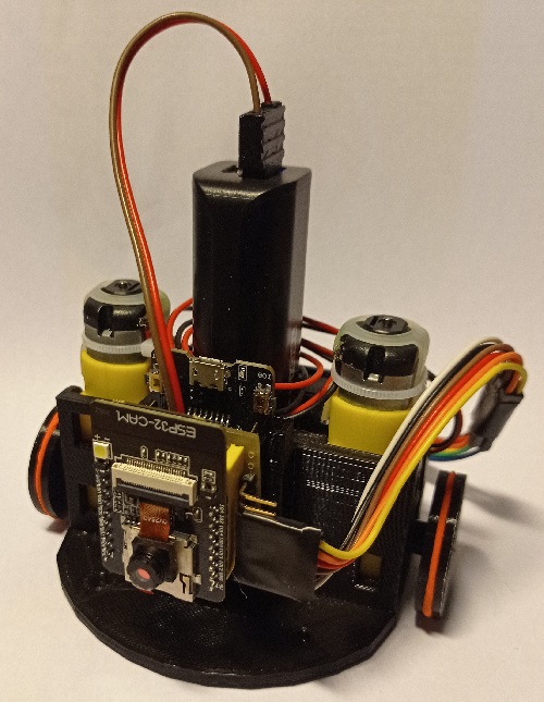
Description:
The ESP-Bot robot is a small mobile platform equipped with an ESP32-cam card, allowing to test computer vision algorithms on a microcontroller !
List of components:
- ESP32-cam board
- ESP32-cam-MB board
- motor driver board
- two 3-6V DC motors with gearbox
- Powerbank
- Padded prototype PCB Boards
- 2 female pin header 8x1
- male bent pin header 8x1
- jumper wires
- 3D-printed chassis
- 2 rubber bands
- 2 felt pads
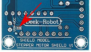
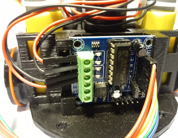
The brain of this robot is an ESP32-cam board which, as its name suggests, contains an ESP32 microcontroller and a small camera. It also includes WiFi and Bluetooth chip and antenna. The ESP32 is a microcontroller clocked at 240Mhz, powerful enough for simple image processing. The ESP32-cam-MB is a small extension board with a USB connection, facilitating programming (via the Arduino IDE) and communication with a PC. The battery is a second-hand TechCharge T2200 powerbank, capable of delivering a current of 1A, and measuring 30x22x94mm. The motor driver board is based on a L293D to drive 2 small 3-6V DC motors with gearbox. It has the advantage of having pins and terminal blocks already soldered. The board must be modified by connecting the component power supply with the motor power supply (otherwise, link the + on the terminal block with the VCC on the connector with a jumper wire).
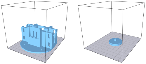
The chassis and wheels are printed from the following models. These models can be printed by low-volume printers (10x10x10cm) and do not require supports. If you're using another powerbank model, you'll certainly need to modify the model (for example with Blender).
- Chassis: robot_vertical_base.stl
- Wheel: robot_vertical_wheel.stl
Robot assembly:
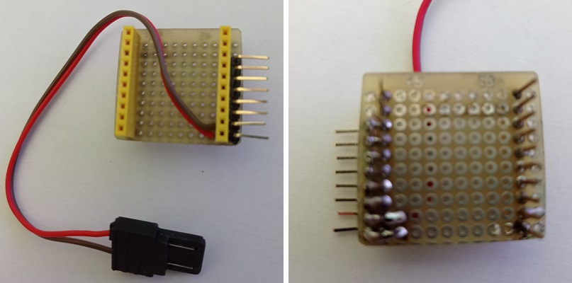
Since the connectors on the ESP32-cam-MB board make the connectors on the ESP32-cam board unusable, it was necessary to create an interface board to fit between the two. For this version of the ESP-bot, a padded test board was used (with size of 10x12 pads). This board uses long-leg pins headers, allowing to connect directly the ESP32-cam-MB. A bent strip "recovers" the ESP32-cam pins. This board can also be used to power the robot with the powerbank without using the USB port, with a printed connector (for example, according to this model). Of course, it's still possible to power the robot with a short USB cable via the ESP32-cam-MB.
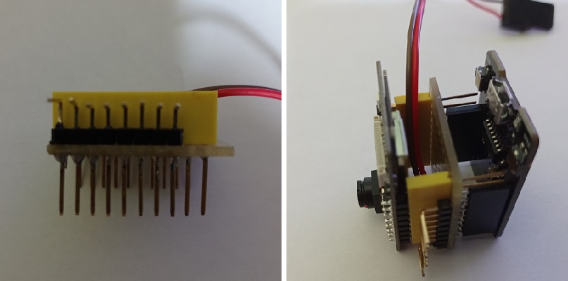
We can then assemble the robot:
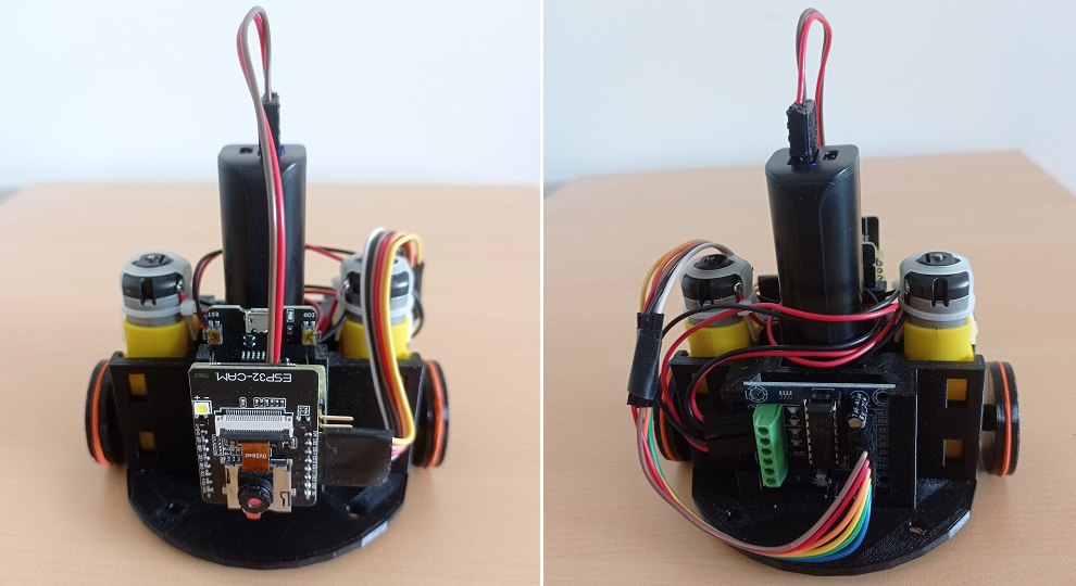
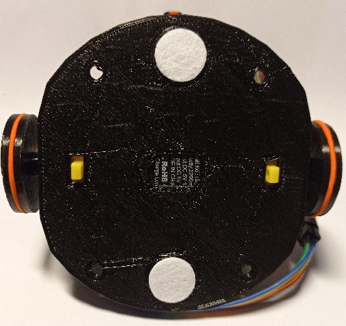
- We start by integrating the two motors into the chassis. If the motors don't fit tightly, one or more layers of adhesive tape can be added to slightly increase the thickness of the motor. .
- Insert the motor driver into the slot at the rear of the chassis. The motor terminal block must be aligned with the notch.
- The ESP32-cam board, the connectors board and the ESP32-cam-MB board are then slotted together. The ESP32-cam-MB board is inserted into the front slot with the USB port facing upwards (the ESP32-cam board is thus upside down).
- Insert the battery in the housing in the center of the robot.
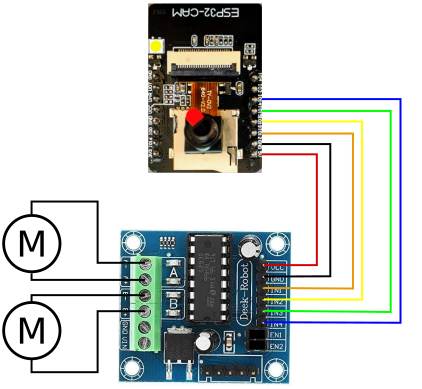
- Connect the motor cables to the driver board, and the six wires between the ESP32-cam board and the motor driver board (see diagram below). Leave the jumpers on the ENABLE pins of the driver board. To enable easy connection and disconnection of the wires, we recommend taping them together with adhesive tape to form a connector.
How to use the robot:
Programming the ESP32 requires installating several extensions to the Arduino IDE. First of all, we need to add the ESP32 microcontrollers to the IDE board manager:
- Access parameters of the IDE (File->Preferences), then, in the field 'Additional Boards Manager URLs', add the following link:
https://raw.githubusercontent.com/espressif/arduino-esp32/gh-pages/package_esp32_index.json
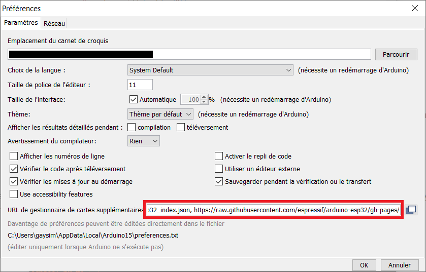
- Download the board models: open the boards manager (Tools->Boards->Boards Managers...). Then, search and install 'ESP32 by Expressif Systems' board models.

- You can now select the 'AI thinker ESP32-CAM' board model. Several properties, such as the microcontroller frequency, can be changed.
To upload an .ino sketch, first make sure that the battery is not connected. It is also advisable to disconnect the motor board (the current drawn by the motors could damage the PC's USB port). We then connect the ESP32-cam-MB board to a USB port on the PC, and select the serial port corresponding to the board in the IDE (Tools->Port). Click on the upload button to compile and upload the sketch.
Once the sketch has been uploaded, disconnect the USB cable and reconnect the motor board. To turn the robot on, simply connect the power cable to the battery. To switch off, disconnect the battery.
Motor control:
The motors are connected to pins 12, 13, 14 and 15 of the board: pins 12 and 13 control the left motor, pins 14 and 15 the right motor. To control a motor, activate the pin of the corresponding direction. To control motor speed, we use the analogWrite function to send a PWM signal to the corresponding pin.
The pins associated with the motors are first declared in the global variables:
							extern int leftmotor1 =  12;

							extern int leftmotor2 = 13;

							extern int rightmotor1 = 15;

							extern int rightmotor2 = 14;
In the Setup function, we declare the motor pins as output and set them to the low state (0):
							pinMode(leftmotor1, OUTPUT);

							pinMode(leftmotor2, OUTPUT);

							pinMode(rightmotor1, OUTPUT);

							pinMode(rightmotor2, OUTPUT);


							digitalWrite(leftmotor1, LOW);

							digitalWrite(leftmotor2, LOW);

							digitalWrite(rightmotor1, LOW);

							digitalWrite(rightmotor2, LOW);
To control the motor, we use the function analogWrite(pin, valeur) with a speed value between 0 (stop) and 255 (maximum speed). In the following examples, we use a variable int speed to define mottor speed:
							// move forward

							analogWrite(leftmotor1, 0);

							analogWrite(leftmotor2, speed);

							analogWrite(rightmotor1, 0);

							analogWrite(rightmotor2, speed);


							// move backward

							analogWrite(leftmotor1, speed);

							analogWrite(leftmotor2, 0);

							analogWrite(rightmotor1, speed);

							analogWrite(rightmotor2, 0);


							// turn left

							analogWrite(leftmotor1, speed);

							analogWrite(leftmotor2, 0);

							analogWrite(rightmotor1, 0);

							analogWrite(rightmotor2, speed);


							// turn right

							analogWrite(leftmotor1, 0);

							analogWrite(leftmotor2, speed);

							analogWrite(rightmotor1, speed);

							analogWrite(rightmotor2, 0);


							// stop

							analogWrite(leftmotor1, 0);

							analogWrite(leftmotor2, 0);

							analogWrite(rightmotor1, 0);

							analogWrite(rightmotor2, 0);
Vertical barcode detector:
This program uses an algorithm to detect remote vertical barcodes. It is a version of the omnidirectional platform detection system, simplified to run on an ESP32. The algorithm detects the position and apparent size of the barcode, allowing the estimation of its distance, and decodes its identifier. However, there is no detection of barcode orientation. The program detects a barcode with a predefined identifier, and enables the robot to follow it.
This type of algorithm allows localization and navigation algorithms using multiple barcodes in the environment.
sketch: ESPbot_barcode_QVGA.ino
barcode pattern: barcode_mini.svg or barcode_mini.png
(to download these files, do a right-click then 'Save target as...')
The barcode identifier to follow is specified on line 4, the motor speed on line 7. The sketch can operate at 240Mhz or 160Mhz (useful for saving battery). To create a barcode, color the gray stripes in black or white to create a 4-bits binary code. The document must be printed without margins. The printed document can be rolled up to form a tube, so that the code is visible from any direction.
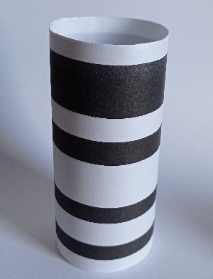
The algorithm scans each column of the image, from top to bottom:
- It looks for a strong negative gradient (from white to black), then for a strong positive gradient (from black to white), recording the vertical positions p1 and p2 of these gradients. In this case, a black band is detected as band 1.
- If this is the first band in the column, or if the code has not been detected, band 1 becomes band 2 (p3‹-p1 and p4‹-p2)
- In this case, the positions of the four bands of the code are estimated from the height of the detected header, and the pixel values compared with a threshold, enabling the band's being to be read (0 if white, 1 if black).
- The digital code is obtained from the four bits. If it is the predefined code, the horizontal position of the column and the header size are recorded.
Once the whole image has been processed, if the number of detected barcode columns is sufficient, the position and height are defined as the average of the obtained values. Depending on the position (left, center or right) and distance (too far, right distance, too close), the robot moves to keep the barcode in the right place.
The program defines the brightness threshold by measuring the maximum and minimum values of the previous column, allowing a certain tolerance to light conditions. In addition, when a barcode is detected on a column, its properties (horizontal position, height of header and bits, identifier) are sent through the serial port, with a rate of 115200 bauds. The message starts with a header composed of a triplet of bytes with values of 255-0-255, this sequence being highly unlikely in normal circumstances. The following section presents a program for displaying barcodes detected by the ESP32.
Barcode display:
This small Java program displays the barcodes detected by the robot. It can be used for debugging and evaluating lighting conditions.
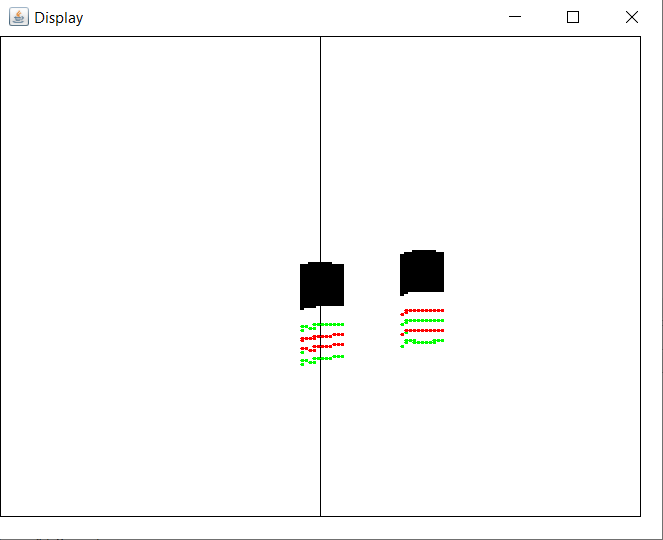
Source code (Java) : ESPbot_barcode_display.zip (require the JSSC library)
To use this program, first create a new Java project with your favorite IDE (Eclipse, IntelliJ..., under Eclipse, 'File'->'New'->'Java Project', give a name then 'Ok'). Then import the three .java files from the above archive into the 'src' folder (under Eclipse, right-click on folder 'src'->'Import...'->'General'->'File System'->'next', then indicate the location of the source files, tick them, then validate).
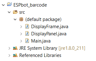
Then associate the jssc.jar file with the project (under Eclipse: right-click on the project->'Build path'->'Configure Build Path...', then 'Add External Jar' and select the file.

On the robot, disconnect the battery and motor board from the ESP32 board, and connect it to the PC via USB. Then use the Arduino IDE to define the serial port number to be used. You'll need to use the Arduino console at least once, and specify a 115200 baud rate (otherwise, the link with the Java program won't work). Next, enter the port number on line 11 of main.java (the name 'ttyUSB' will be automatically changed to 'COM' on Windows systems). Present one or more barcodes to the robot, they should appear in the display.