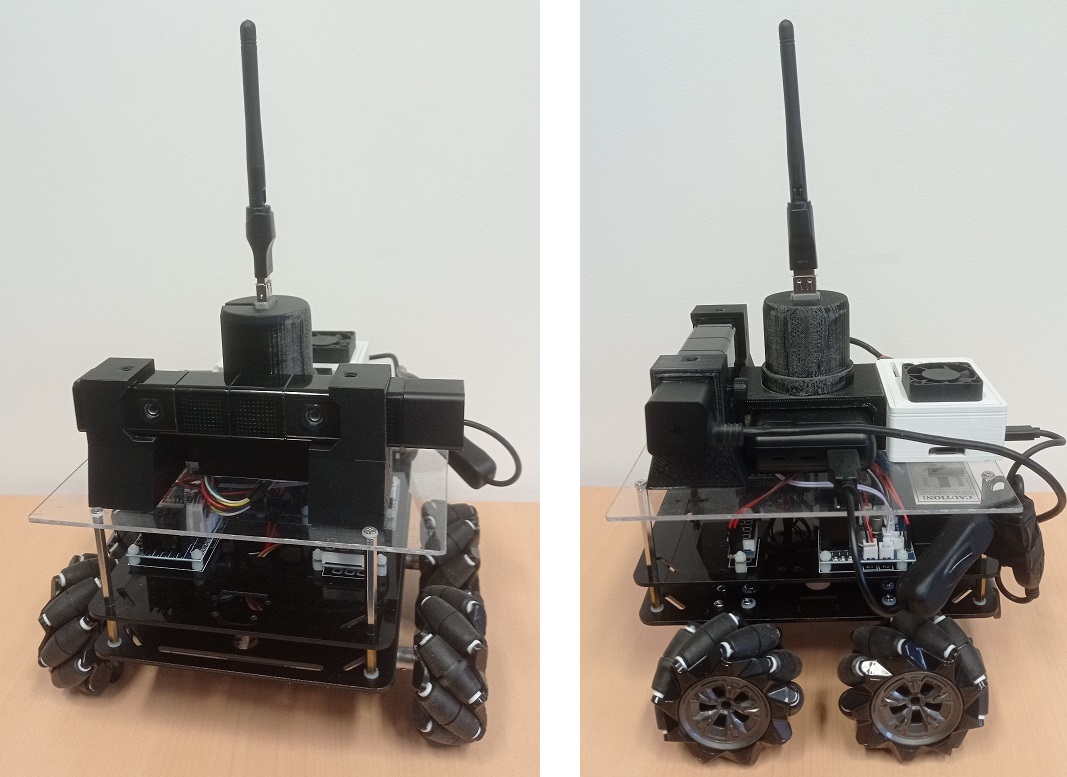
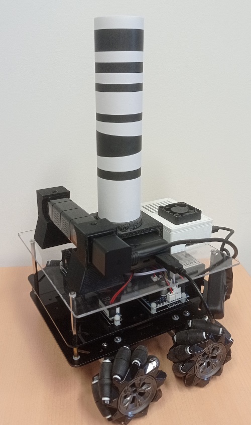
This robot was designed to test and validate our bio-inspired navigation models in a real environment. The choice of platform was dictated by various constraints: omni-directional movements to simulate the movements of a person, affordable to be able to equip with a swarm of robots, and of sufficient size to be equipped with a nanocomputer and a binocular camera. We chose the Mecanum Wheel platform produced by Osoyoo. This platform was then equipped with an additional stage to support additional components.
The Osoyoo Mecanum Wheel platform provides an interesting base for our test platform: it is relatively simple to assemble and offers omni-directional movement. Its architecture, based on common components (Arduino and L293 motor control board), makes it easy to interface with additional components.
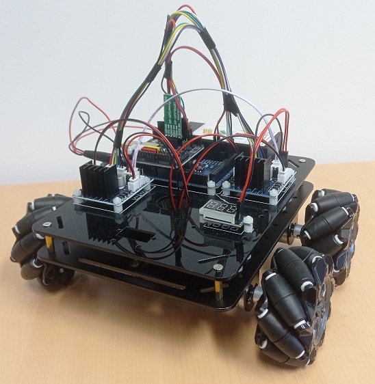
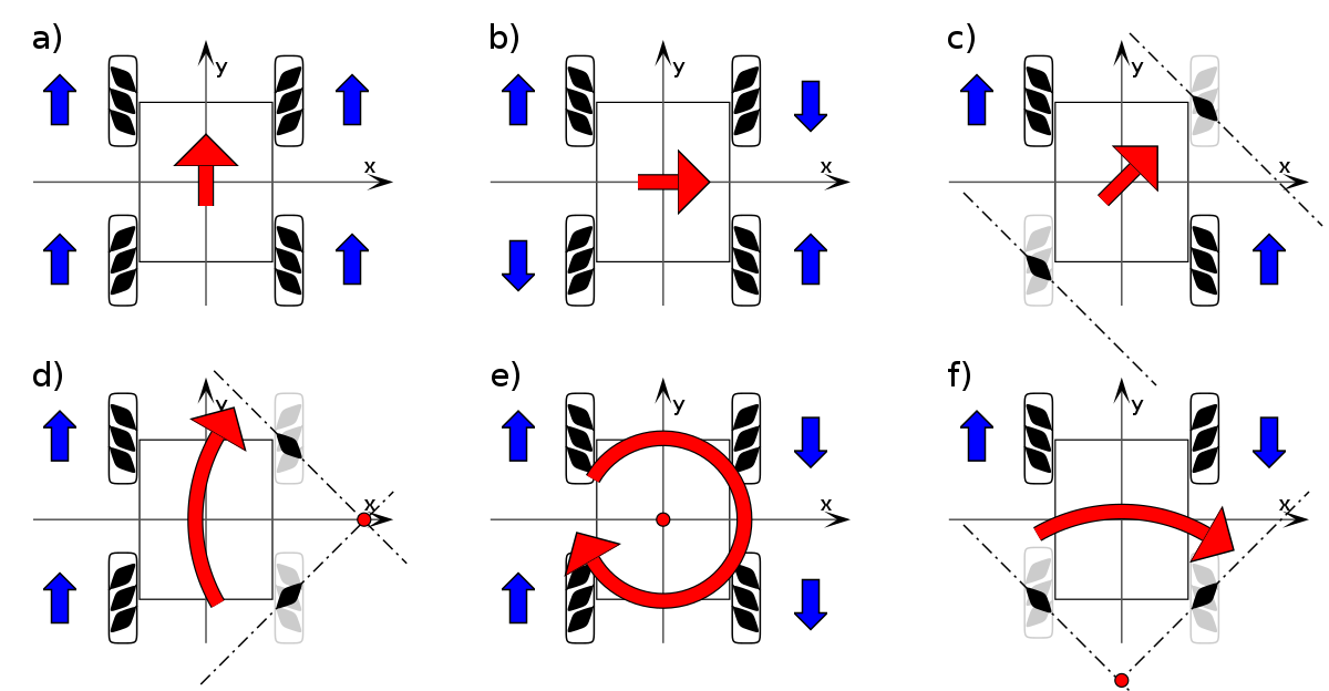
The platform is equipped with four 'mecanum' wheels, that are wheels with small internal rollers. Unlike omni-directional wheels (or holonomic wheels), whose rollers are perpendicular to the wheel axis, mecanum wheels have rollers inclined at 45° to the axis. This particular configuration means that a robot equipped with four of these wheels can move in all directions, with one particular direction (forwards/backwards) generating no additional friction due to the rolling of the internal rollers, unlike three-wheeled holonomic robots, whose rollers generate additional friction in all directions.
Demonstration of the platform's movement capabilities, here controlled with a gamepad:
Source code:
- Arduino code: robot_control_bluetooth.ino
- Java interface:
Mouse control: robot_control_mouse.zip (requires the JSSC library)
Gamepad control : robot_control_gamepad.zip (requires the JSSC and jinput libraries)
Instructions :
- Connect the robot to your PC, following the Osoyoo tutorial
- Upload the .ino code to the robot's Arduino
- Create a new Java project, and import files from one of the two archives
- Using the Arduino IDE, determine which port the Bluetooth dongle is connected to: the program sends the word "test" continuously, which you can read using the serial monitor. Then select the port for connecting to the Arduino throught USB to release the Bluetooth port.
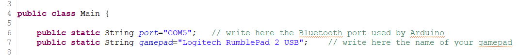
- In the Main class, indicate the port used by the Bluetooth dongle (line 6)
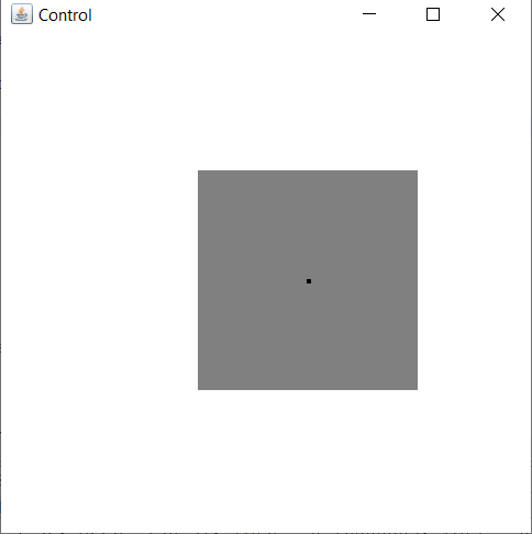
- Run the java program. A window should open
- Click in the window to start a virtual joystick. Without releasing the button, move the cursor around the initial point to control the robot: left button for forward/backward/translations and right button for forward/backward/rotations. The robot stops when you release the button.
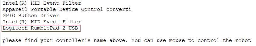
- Find the name of the device in the list displayed in the terminal
Integration of a GY-87 inertial measurement unit (IMU) :
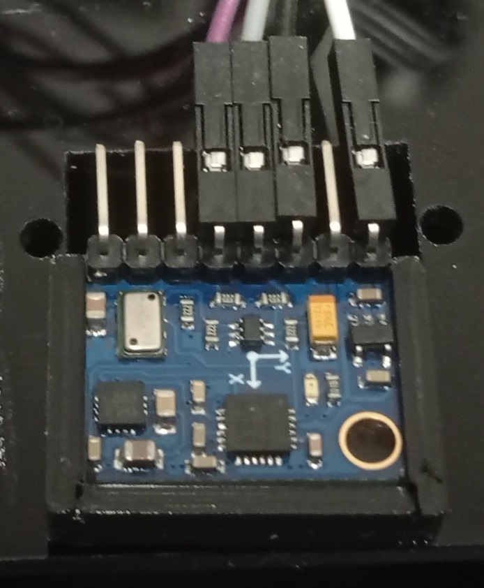
The GY-87 inertial measurement unit is a development board equipped with an MPU6050 accelerometer and gyroscope for measuring accelerations and rotations on 3-axis, a HMC5883L magnetometer that can be used as a compass, and a BMP180 barometric pressure sensor. The card can be powered from either 5V or 3.3V. These sensors provide a relatively accurate estimation of the robot's movements in its environment.
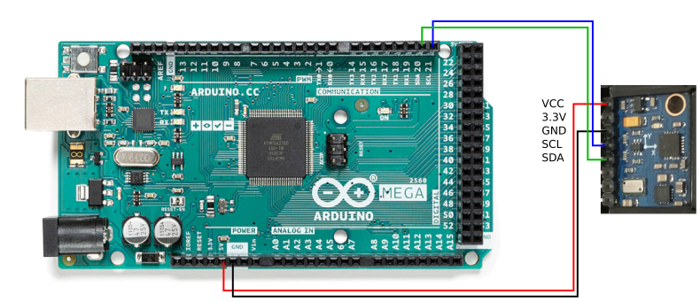
Connecting the IMU board to the Arduino is simple:
- the power pins are connected to the 5V and Gnd pins on the Arduino.
- sensor data is transmitted through the SCL and SDA pins, connected to the corresponding pins on the Arduino ('SCL 21' and 'SDA 20' pins on the robot's Arduino Mega).
You can find out more about how to integrate this IMU card on Olivier Georgeon's website.
The IMU board is held in a 3D-printed support and positioned on the front of the robot. You will find below the model of the support and the Arduino and Java codes for reading the information from the board.
Code source :
- Support model: IMU.stl
- Arduino code: robot_control_bluetooth_IMU.ino
- Java interface:
Mouse control: robot_control_mouse_IMU.zip (requires the JSSC library)
Gamepad control: robot_control_gamepad_IMU.zip (requires the JSSC and jinput libraries)
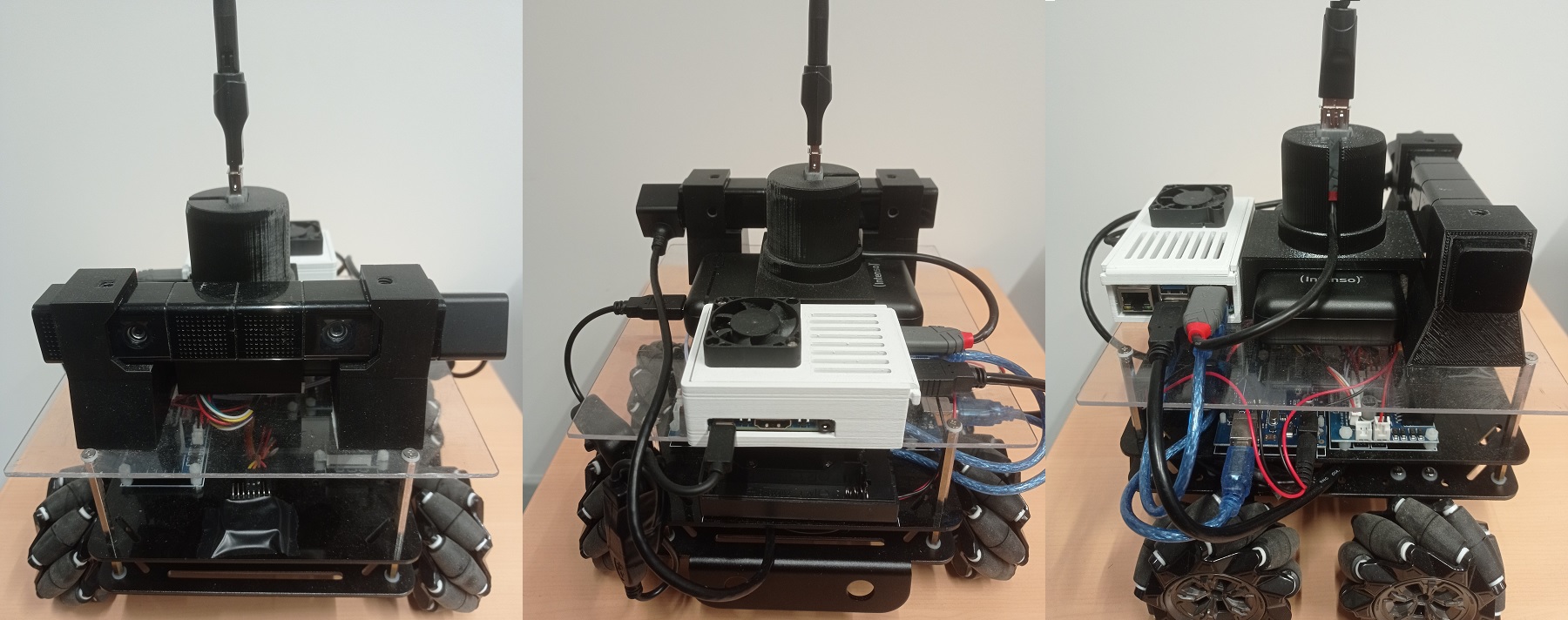
In order to make the robot autonomous, while enabling image processing and localisation, the platform is equipped with a nanocomputer. As the famous Raspberry Pi 4 was out of stock at this time, we chose an equivalent model: the Banana Pi M5. This computer doesn't have a Wi-Fi connection, so a Wifi dongle has to be added. We used a dongle based on a Ralink RT5370-MT7601 chipset (note that the RT5370-MTK7601 chipset does not work with the version of Raspbian that we used). The binocular camera is a Playstation 4 (PS4Eye) camera modified to plug into a USB3 port (tutorial available here). The system is powered by a 20Ah powerbank, independent of the motors battery. The system communicates with the robotic platform via a USB connection with the Arduino board of the robot.
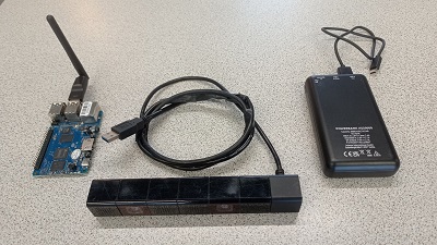
The additional components are placed on a 5mm-thick plexiglass plate held to the chassis by spacers, and held in place by 3D-printed mounts. The Banana Pi case is based on this model. The battery support is designed for an Intenso XS20000 powerbank, of dimensions 128 x 70 x 25,2 mm. This support also holds the WiFi dongle, connected to the Banana Pi by a 10cm USB extension cable. The camera mounts are designed for version 1 of the PS4 eye. Two must be printed, one of which must be reversed (symmetrical mounts).
- Battery support: batterie_support.stl
- Camera support: camera_support.stl

From a software point of view, the robot's Banana Pi runs under a version of Raspbian adapted to this board (version 2023-05-03, with a kernel 5.17.2-meson64) available on this wiki. We recommend installing the following software:
- openssh-server: to connect via ssh from another computer,
- xrdp: to connect remotely to a graphical session (e.g. Remmina),
- OpenJDK: to use the code provided on this page. The robot uses version 17,
- Eclipse: an IDE for developing in Java directly on the robot,
- Python3: to use the program that transfers the firmware to the camera,
- guvcview: for testing the camera,
- libjssc-java: a Java library for using the serial port.
The computer communicates with the Arduino through USB serial port. Here is the source code for the Arduino and a Java class used as an interface:
- Arduino code: robot_control_usb.ino
- Java interface: Robot.java (requires the JSSC library, on the robot, you will need to use the .jar available in /usr/share/java/ after installing libjssc-java)
You then need to install OpenCV for Java. You can follow this tutorial. However, after the CMake command, make sure that the compiler has found the ANT and JNI executables. You should also ignore the make clean command to avoid deleting the generated .jar file. If all has gone well, after a long compilation, the .jar file should be in the /home/pi/opencv/build/bin folder, and the .so libraries in the /home/pi/opencv/build/lib folder.
Use of the PS4Eye camera:
The PS4Eye requires the upload of a firmware before use. The first step is to disconnect and reconnect the camera. You can test whether the camera is recognised by running the lsusb command, which result should display the camera:
ID 05a9:0580 OmniVision Technologies
Otherwise, you have to check the wire connections
The firmware can then be uploaded using the code provided here:
						 cd Firmware_loader

						 sudo python3 ps4eye_init.py
If everything goes well, the following message should be displayed:
PS4 camera firmware uploaded and device reset
The camera can then be used as a simple webcam (here, with guvcview):
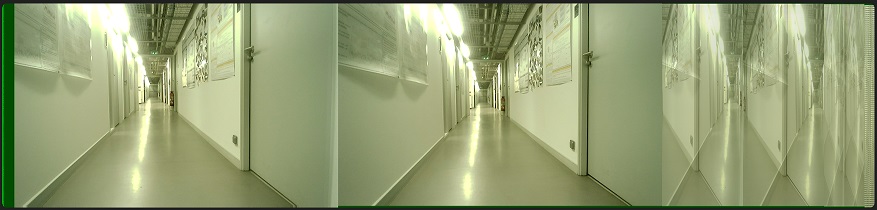
The images provided by the camera have a size of 3748x808 pixels, and include images from the two cameras, each having a size of 1280x800 pixels, as well as reduced versions of these images. The following code is used to obtain two images from the camera stream:
- camera.zip
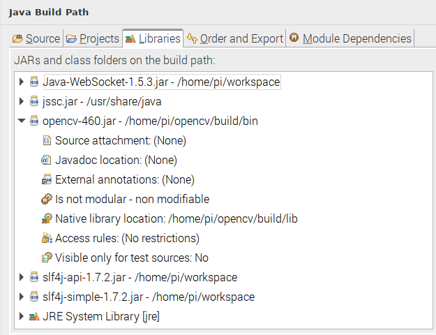
To use this code, create a new project (in Eclipse, for example), and import the files from the archive above. Associate the opencv.jar library (Build path->Configure build path->Libraries->add external JAR) obtained after compilation, then specify the location of the native libraries:
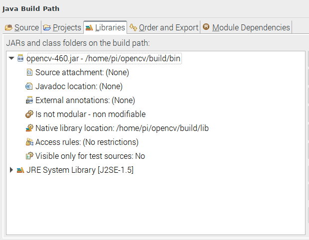
In the Main class, it is possible to specify the camera number, the framerate (if the image is too dark, decrease the value to 30fps to increase the exposure time), and activate automatic brightness adjustment (only under Linux).
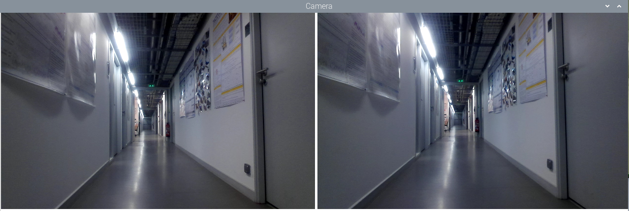
Running the program opens a window displaying the two separate left and right images:
A simplified stereoscopic vision system:
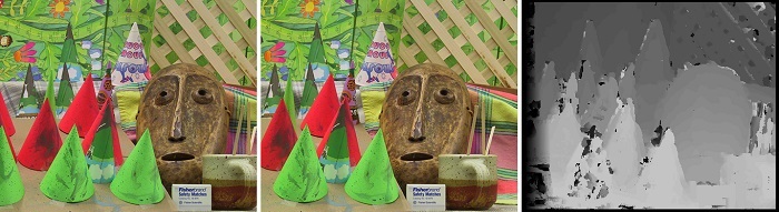
Stereo matching algorithms compare two stereoscopic images of a scene, then determine the position of each pixel of the first image in the second image. The difference in position, or disparity, is used to compute the distance of this point. Stereo matching algorithms can be used to obtain a depth map of the scene.
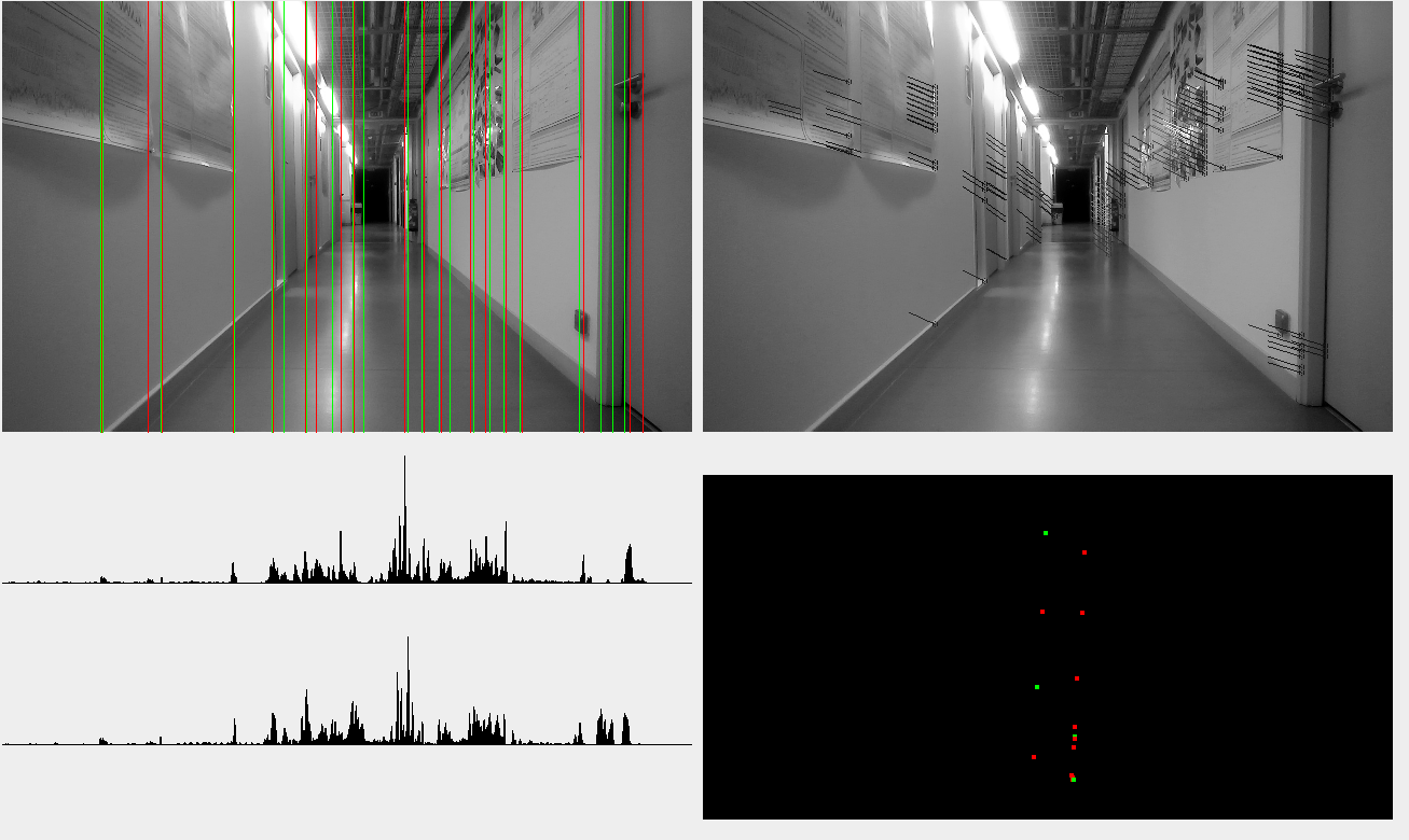
However, stereo matching algorithms are particularly heavy, especially for a nanocomputer. As we are focusing on two-dimensional navigation, the disparity map is not necessary: only the position of points of interest in the plane is required. We propose to use the vertical lines visible in the scene: they are easy to detect, omnipresent in the environment, and localisable using stereo images. In a 'top view' map, these vertical lines become points of interest that can be used to define the position.
The algorithm uses the following steps:
- detection of vertical edges,
- detection of main vertical lines, by accumulating des principales lignes verticales, by accumulating the edges of the same column of pixels,
- filter lines to keep only the most pronounced ones,
- get the edge points that are on these lines,
- use an optic flow algorithm on these points, between left and right images,
- compute the points' positions from disparity,
- get the median distance of each vertical line,
- project the lines on the navigation map.
We can note the use of an optical flow algorithm (here, the calcOpticalFlowPyrLK function of OpenCV library), diverted from its usual use: rather than measuring the movement of points between two consecutive images, we measure the disparity of these points between the left and right images. Also, the points are separated according to the direction of the contour gradient, giving two types of points of interest.
This algorithm allowed tests of our bio-inspired navigation system in a real environment, initially on a laptop PC, then on the robotic platform.
The following code can be used to obtain the navigation map from the images from a PS4Eye. It runs at around 40-50 fps on a PC with an i5-10210U CPU, and at around 8-12 fps on a Banana Pi M5.
- stereo.zip
Like before, you will need to associate the OpenCV libraries with your project, and possibly modify the parameters in the Main class. For greater efficiency, you will also need to change the maximum and minimum height (in cm) of considered points according to the height of the camera, in the StereoVision class, line 277.
A web interface control:
In order to perform tests on the robot without using a remote graphics session, we developed a web interface based on a minimalist web server. This server provides a single web page with functions for interpreting the information from the robot and drawing the contents of the displays in a web browser. The server also connects to the client using a Java websocket allowing a communication between the client and the server.
This server has three components:
- Server.java: this is the Web server itself. It receives requests from the client and returns the HTML page. It also initialises the next two modules.
- DataWebSocket.java: a class initialising a websocket between the client and the server. The onMessage function is used to process messages from the client. The broadcast function is used to send a message (in the form of strings of characters) to the client.
- VideoSocket.java: a socket dedicated to sending a video stream. This module runs on a separate thread, and sends the image from the left camera every 100ms.
To communicate with the client, the protocol consists of a keyword followed by arguments separated by spaces.
On the server side, messages are processed in the onMessage function of the DataWebSocket class:
- 'robot' is used to send direction commands to the robot (e.g. 'robot forward'),
- 'system' is used to control the application. The 'system stop' command stops the application.,
- 'message' displays a message on the console.
On the client side, processing takes place in a JavaScript function associated with an eventListener.
- 'framerate' sets the current framerate in the interface,
- 'context' provides the point context's content as a set of triplets 'type posx distance'.
The interface with the robot's Arduino is similar to the interface used for joystick control, with messages sent to control the motors, and a Listener to receive movement information, if an IMU is connected to the Arduino.
Source code:
- robot_control_usb.ino
- robot_control_usb_IMU.ino
- stereo_server.zip
To use this code, you will need to associate the project not only with the OpenCV libraries, but also with the JSSC.jar library located in the /usr/share/java/ folder (install the package if the library is not there) to communicate with the robot's Arduino, and with the Java-WebSocket.jar, slf4j-api.jar and slf4j-simple.jar libraries used by the server. In the Main class, you will need to specify, if necessary, the port used by the Arduino (by default: "/dev/ttyACM0") and the location of the HTML page (by default: "./"). It is also possible to enable/disable the window displaying the camera image and the context.
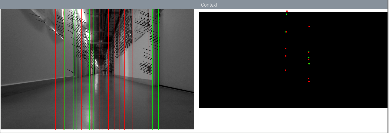
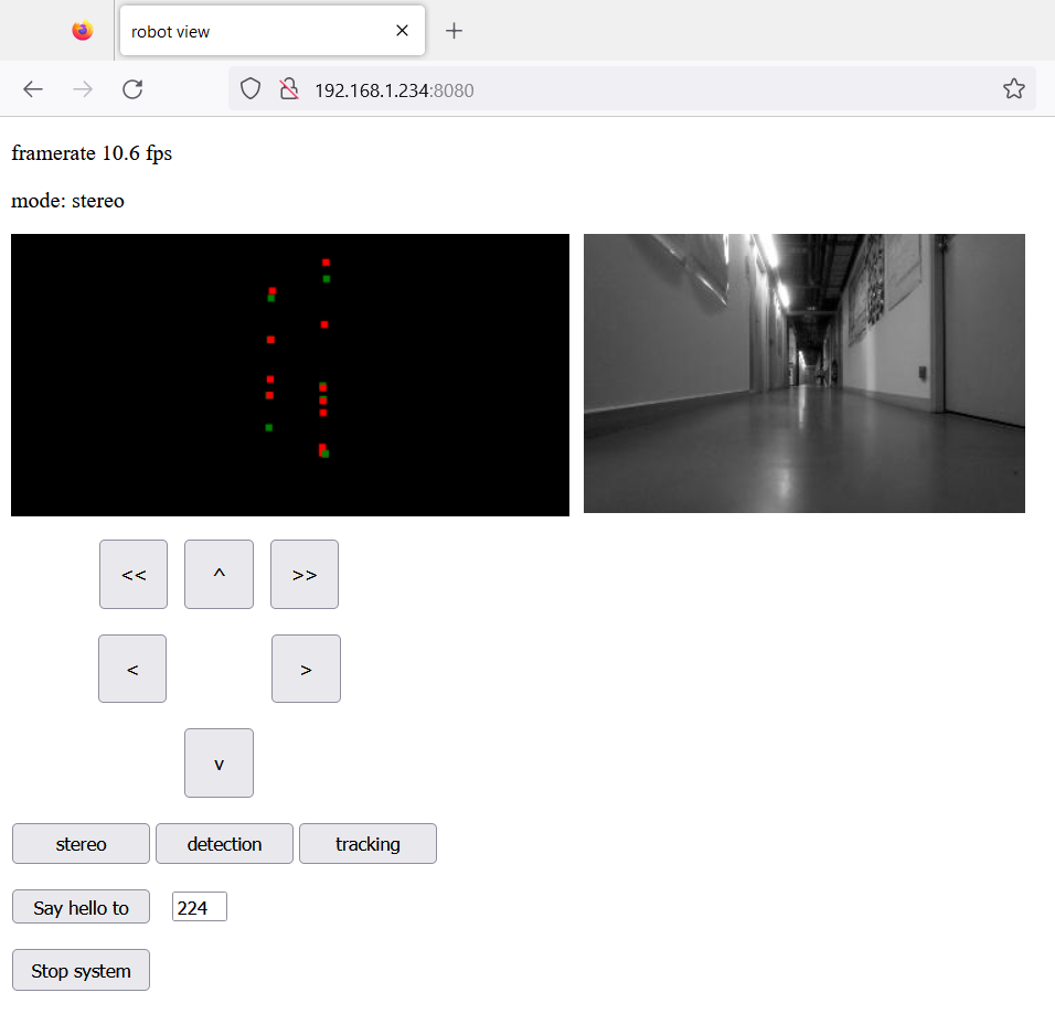
The nanocomputer and the client PC must be connected to an open WiFi network. Once the Java application has been launched on the robot, the client PC must simply connect with a Web browser to the robot's address, using port 8080 (for example 192.168.1.100:8080). The Web interface displays the framerate, the image from the left camera and the context reconstructed from data coming from the robot.
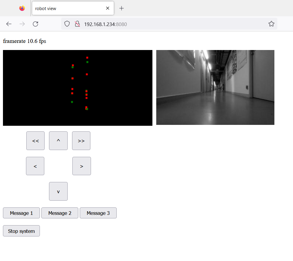
The robot can be controlled using the six buttons. Three buttons have been added to illustrate the possibility to send messages to the server. The content of the messages can be modified in the index.html file, in the 'sendMsg' JavaScript function, and their processing, in the onMessage function of the DataWebSocket class. If an IMU is connected to the Arduino, the robot corrects its trajectory as it moves forward to keep its orientation.
If the application works correctly, it is possible to export an executable JAR, which can be launched from a simple SSH session.
The study of our navigation models also focuses on the distribution of the model over several robots. This distribution is designed to spread resource requirements, and therefore the individual resources needed for each robot. This principle implies that, while one robot is guiding the group, the others can be assigned other tasks, while following the guide robot. We have developed a very simple but effective tracking system based on a vertical barcode inscribed on a paper tube placed at the top of each robot. This barcode contains a 4-bits code and provides an approximation of the orientation (see figure below).
A visual localization system:
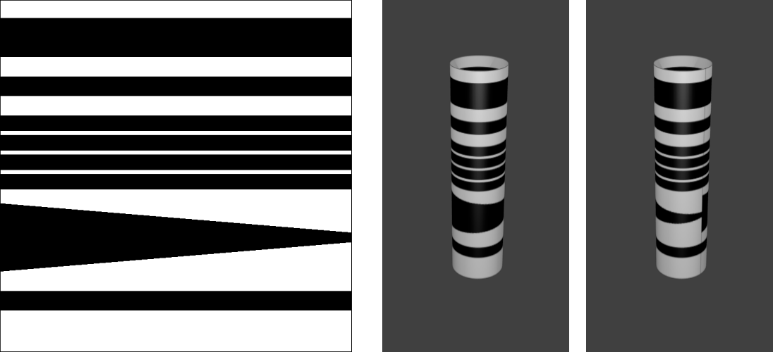
This localisation system allows robots to locate each other, but can also be used as a beacon for navigation-related projects. It uses vertical barcodes inscribed on paper tubes so that they can be seen from any direction, unlike AR markers (or ARtags). However, to measure distances, the barcode must be at the same height as the camera.
These barcodes have a header and footer allowing their detection, but also to estimate their distance through their apparent size. The content includes a 4-bit code, allowing to identify the bearer of this code. A band of variable height can also be used to estimate the orientation of the barcode, the height of the visible part being dependent of the point of view.
The algorithm scans each column of the image, from top to bottom, and looks for horizontal edges. When a strong negative gradient (change from white to black) is detected, the algorithm then looks for a strong positive gradient (change from black to white), enabling a black band to be detected.
When two bands are detected, their heights and spacing are compared: the first band must be twice as high as the second, and the spacing must be equivalent to the height of the second band. If these ratios are respected, a header is detected.
Based on the height of the header, the algorithm determines a search window for the footer. If a black band is detected in this window, a barcode is considered as present.
The algorithm then determines the position of the four bands of the binary code, and reads the colour on these four positions. The obtained binary code gives the barcode identifier.
A search window for the variable band is then defined. The relative height of this band in relation to the height of the code is measured.
Once the image has been scanned, the columns with identical codes are merged to obtain the horizontal position and orientation of the barcode.
This sensor was integrated into the robotic platform application, which now offers three operating modes:
- the mapping mode, which generates a context of points of interest using stereoscopic vision,
- the scanner mode, which detects and displays visible barcodes,
- the tracking mode, which makes the robot following a barcode.
These different modes can be selected via three buttons on the web interface. New keywords have been added to the communication protocol: on the client side, 'changemode' is used to change the application's operating mode. On the server side, 'mode' is used to display the current mode in the web interface.
The scanner mode displays visible barcodes, showing the identifier, estimated orientation, horizontal position and distance (given here by the apparent height). This mode disables the stereoscopic vision system, allowing the application to run at 25 to 30 fps.
The tracking mode makes the robot following a specific barcode. The identifier of the barcode to be tracked must be specified in the parameters of the Main class ('CODE' parameter). The tracking system simply maintains the position of the barcode at a certain distance and orientation from the robot.
Tracking mode through interface view:
Tracking mode through observer view:
Source code :
- robot_control_usb.ino
- robot_control_usb_IMU.ino
- stereo_server_scanner.zip
- barcode.svg
The code is used in the same way as for the server version: the project must be associated with the OpenCV, JSSC.jar, Java-WebSocket.jar, slf4j-api.jar and slf4j-simple.jar. The port used by the Arduino and the location of the HTML page must then be specified in the Main class. The application can be exported as an executable JAR for use with an SSH connection.
A system for communication between robots:
To allows the robots of the fleet to communicate with each other, we added a communication system. This system is based on the previously developed server, and uses POST requests to send messages.
The robots are identified by an identification number defined as the fourth number of their IP address on the network. For example, a robot with an IP address of 192.168.1.120 will have the identifier 120. The communication protocol is defined as follows: a communication consists of the sender's number and the message in the form of string of characters, separated by a semicolon. The message consists either of a single keyword, or of a keyword followed by parameters. In the latter case, the keyword and its parameters are separated by a semicolon, and the parameters are separated by commas. The following example shows a valid syntax, where 120 is the sender's address, 'control' the keyword and 'wait' and '5000' are the parameters:
"120;control;wait,5000"
The Server class is modified to handle POST requests: a message received is split into an identifier, a keyword and a list of parameters. The server stores the information from the last received message for later processing (the message can then be deleted using the clear() procedure). It is also possible to process the message directly in the PostHandler procedure of the Server class.
For sending messages, a new class has been added: the Talky class. This class defines the robot's identifier from its IP address and provides a sendMsg procedure for sending a message to another robot. The procedure takes the recipient's identifier and the message as arguments (the procedure automatically adds the sender's identifier to the message before sending).
A text field and a button were added to the Web interface to illustrate the sending of a message to a robot with a specified identifier. This message will be displayed in the terminal of the recipient robot. Note the addition of the keyword 'message' in the Web interface to request the server to send a message via the sendMsg procedure.
Source code:
- robot_control_usb.ino
- robot_control_usb_IMU.ino
- stereo_server_scanner_talky.zip
The use of this code is identical to the previous version, and requires to associate the same libraries to the project and to specify the same parameters.
This communication system was used to study the possibilities of mapping and guidance with multiple robots. Here, one robot is remotely controlled and maps the environment. The second robot follows the first, and exchanges positions at regular intervals. The communication system allows the robots to synchronise during the exchange. Each robot records only part of the map. Our bio-inspired navigation model allows this distribution, but also an exploitation of such a distributed model.