Description:
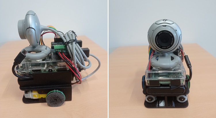
The robot Johnny 3 is a small Raspberry Pi-based robotic platform designed to test computer vision algorithms, while remaining as affordable as possible.
List of components:
- Raspberry Pi with case
- SD card of at least 8GB
- webcam usb
- Wifi Dongle
- Powerbank ables to provide 2A
- motor driver board
- two 3-6V DC motors with gearbox
- jumper wires
- 3D-printed chassis
- 2 rubber bands
- felt pad
For the Raspberry Pi, I used my Raspberry Pi 2B, running Raspbian 32-bit. A Raspberry Pi 3 can also be used. For version 4, you'll need a battery capable of supplying at least 3A.
The Wifi dongle is a TP-Link-WN725N Nano, with 150Mbps bandwidth, chosen mainly for its low price and compact size.
Installing the dongle's drivers on Raspbian is quite complex, but possible by following this tutorial. Note that the Raspberry PI 3B has a built-in wifi antenna.
The battery used is a Revolt PB-160 with a capacity of 5000mAH and able to provide a 2,4A current. It also has the distinctive feature of being comparable in size to the Raspberry PI board.
The robot can use any commercially available USB webcam. However, it is recommended to use a model with a flat support.
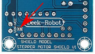
The motor driver board includes an L293D to drive 2 small 3-6V DC motors with gearbox. The board must be modified by connecting the electronic power supply with the motor power supply (otherwise, you can connect the Vin on the motor connector to the VCC on the control connector with a wire).
The chassis and wheels are printed from the following models. These models can be printed by low-volume printers (10x10x10cm) and do not require supports. However, a raft is recommended.
- Chassis: robot_base5.stl
- Wheel: robot_wheel5.stl
- Driver holder: driver_support.stl

Robot assembly:
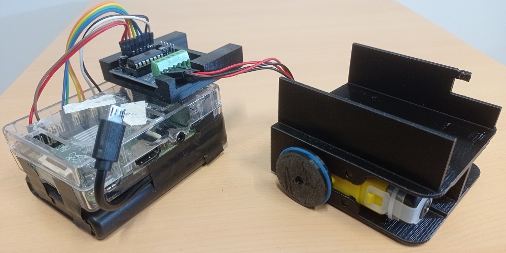
- We start by integrating the two motors into the chassis. If the motors don't fit tightly, one or more layers of adhesive tape can be added to slightly increase the thickness of the motor. The cables must pass through the opening at the rear.
- Stack and attach the Raspberry Pi case and battery using double-sided tape. The Raspberry Pi's USB ports and the battery ports should be on the rear of the robot. The USB cable should exit the battery, then run along the edge of the battery to the Raspberry PI power port.
- Secure the Raspberry/battery unit in the slot on the chassis using double-sided tape. The USB power cable should exit through the notch in the front-left of the chassis, and plug easily into the Raspberry's power port. Next, connect the Wifi dongle to one of the Raspberry Pi's USB ports.
- Insert the motor board into its holder. The terminals must be aligned with the notch. The holder is then attached to the Raspberry Pi case using double-sided tape, without masking the GPIO opening, and with the two rods protruding from the case towards the rear.
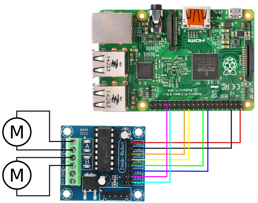
- Connect the motor cables to the driver board, and the eight cables between the Raspberry Pi and the driver board (see diagram below).
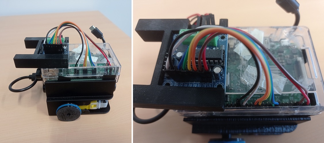
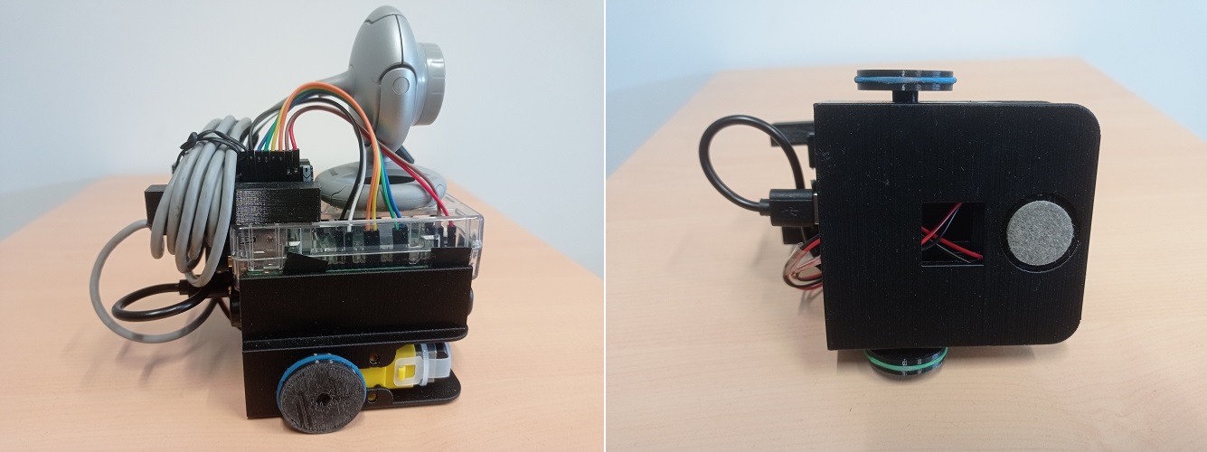
- Add the wheels to the motor axles, then place the rubber bands to act as tires. Finally, add the felt pad to the notch in the front, below the chassis.
Software installation:
From a software perspective, the robot's Raspberry Pi 2 runs Raspbian 11 Bullseye 32-bit version, installed on an SD card. Once the SD card is inserted in the Raspberry Pi, connect a monitor to the HDMI port, a mouse and keyboard, and connect an Ethernet cable to access network. During installation, it's best to use the Raspberry Pi's mains charger (to avoid running out of battery during installation).
Once on the Raspbian desktop, start by installing the Wifi dongle driver (only on Rapberry Pi that don't have their own antenna) by following this tutorial.
Unplug the Ethernet cable, then connect to your Wifi network. Open a terminal, then enter the ifconfig command to obtain the Raspberry Pi's IP address in the network.
The necessary software is then installed. We recommend installing the following software:
- openssh-server: to connect via ssh from another computer,
- xrdp : to connect remotely with a graphics session (e.g. Remmina),
- OpenJDK : to use the programs provided on this page. The robot uses version 17,
- Python3 : to program in Python,
- guvcview : to test the camera.
Then install OpenCV by following this tutorial.
However, after the CMake command, make sure that the compiler has found the ANT and JNI. You should also skip the make clean command to avoid deleting the generated .jar file. If all has gone well, after a long compilation, the .jar file should be found in the /home/pi/opencv/build/bin folder, and the .so libraries in the /home/pi/opencv/build/lib folder.
Turn off the Raspberry Pi, then unplug the screen, mouse and keyboard. Restart it, then wait for the dongle to flash. You can now connect to the Raspberry Pi from another PC connected to the same local network, either via SSH or a remote desktop program (such as Remmina). To connect via SSH, enter the following command, using the Raspbeery Pi's IP address (in this example 192.168.1.10), then enter your password (password is not displayed in the console, this is normal).
ssh -X pi@192.168.1.10
This opens a command-line session on the Raspberry Pi. For a graphical session, use Remmina under Linux or Remote Desktop under Windows, then enter the IP address, login and password, to open a remote graphical session from your PC.
How to use the robot:
We can now send and execute Java and Python programs. To keep things organized, we can create two folders, 'Java' and 'Python', in the User folder, using the graphical interface or the command lines:
							mkdir Java

							mkdir Python
You can then send .jar or .py programs using the SCP command on the command line. To do this, on the PC, open another console in the folder where the program is located, then enter the following command line:
scp my_program.jar pi@192.168.1.10:/Java
ou
scp my_program.py pi@192.168.1.10:/Python
The Raspberry Pi password is requested to enable the transfer. This must be entered in the console (it is not displayed). With a graphical interface, it is also possible to transfer programs using a USB key, by copying the programs to the key from the PC and then pasting them into the folders on the Raspberry Pi.
The programs are then run with a command line. On an SSH console from the PC, or on a console from a remote raspbian desktop, we use:
cd ~/Java
or
sudo java -jar my_program.jar
							cd ~/Python

							sudo python3 my_program.py
The 'sudo' command is only required if the program requires an access to the Raspberry PI's GPIO port. If the program uses X11 forwarding, the following error may occur :
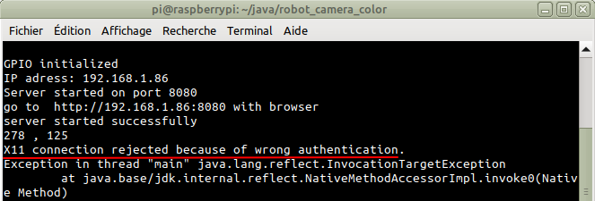
The problem is easily solved with the following command:
export XAUTHORITY=$HOME/.Xauthority
To turn off the robot, use the following command, then, when the Raspberry Pi LEDs stop flashing, disconnect the USB power cable.
sudo halt
Test programs:
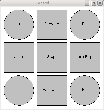
The following programs can be used to test the robot's motors and camera. The robot_motor_test program displays a window with buttons for controlling the motors. The square buttons can be used to move the robot forward, backward and rotate, while the round buttons can be used to control the motors independently.
Source code:
- JAR file: robot_motor_test.jar
- Java code: robot_motor_test.zip
To use the JAR file, first send it to the robot. On the PC, open a console in the folder where the file is located, then enter the following command in a new console (using the Raspberry Pi address):
scp robot_motor_test.jar pi@192.168.1.10:/home/pi/Java
Then, on the console connected via SSH, run the program with:
							cd ~/Java

							sudo java -jar robot_motor_test.jar
To use Java code, it is recommended to use an IDE (Eclipse, IntelliJ...), then create a new project. The .java files are then imported into the project. This program requires the pi4j library (with Eclipse: right-clic on the project->Build Path->Configure Build Path, then in the libraries tab, clic on 'Add External Jars...').

The class MotorControl initializes the GPIO ports used to control the motors, and provides a low-level function to control speed and direction of the two motors: the function setMotor(int vg,int vd) allows defining the speed and direction with values between -100 and +100. the function stop() stops the two motors.
The class Robot provides higher-level functions to control the robot, in particular move(int g, int d, int time) that makes the robot moving for a defined time (in milliseconds).
The program can then be exported in JAR format and uploaded on the robot (with Eclipse: right-click on the project->Export...->Java->Runnable JAR File->Next, then select the correct Main file, the destination location, and the 'package required libraries into generated JAR' option, before finalizing by clicking on 'Finish').
the program robot_camera_test opens a window displaying the robot's camera image.
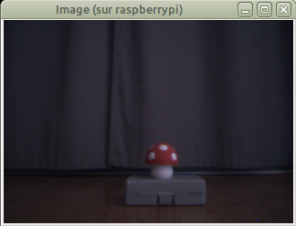
Source code:
- JAR File: robot_camera_test.jar
- Java code: robot_camera_test.zip
To use the JAR file, open a console, on the PC, in the folder where it is located, then enter the following command in a new console :
scp robot_camera_test.jar pi@192.168.1.10:/home/pi/Java
Then, on the console connected via SSH, run the program with :
						cd ~/Java

						java -jar robot_camera_test.jar
To use the Java code, you need to associate this program with the OpenCV library (you'll need to install it on your PC first), and specify the location of the native libraries (.so under Linux, .dll under Windows).
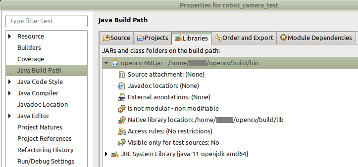
The class Camera initializes the robot's camera and loads OpenCV libraries. The function read() grab a new frame from the camera, and the function setBufferedImage converts the image from Mat format (OpenCV) to BufferenImage to be displayed.
A Web interface:
This program enables the robot to be controlled from a web browser (Firefox, Chrome, Opera...) while receiving the camera's video stream. The program contains a simple web server hosting an Html page, and communicates with the client using websockets to receive user commands, send information for display, and send the camera's video stream.
The web interface (left) is used to control the robot using the four buttons. The display shows the camera's video stream (note that the number of images per second is low due to the low light conditions, with the camera increasing the exposure time for each image).
Source code:
- HTML page: index.html (right-click -> Save link as)
- JAR file: robot_camera_server.jar
- Java code: robot_camera_server.zip
As the program requires a specific document (the HTML page), it is advisable to create a specific subfolder for this project. On the SSH console (or directly on a remote desktop), for example, you can create the folder with the following commands:
						cd ~/Java

						mkdir robot_camera_server

						cd robot_camera_server
Then, from the PC, we open a new console in the folder containing the JAR and HTML files, and enter the following SCP commands, using the Raspberry Pi's IP address and password:
						scp robot_camera_server.jar pi@192.168.1.10:/home/pi/Java/robot_camera_server

						scp index.html pi@192.168.1.10:/home/pi/Java/robot_camera_server
From the SSH console (or from a console on a remote desktop), run the program with the following command:
sudo java -jar robot_camera_server.jar
The web server starts, then displays its address in the SSH console. From any PC, tablet or smartphone connected to the same network, you can open a web browser and enter this address in the address bar, to display the interface page. You can then control the robot using the arrow keys. Stop the program by clicking on the 'stop system' button (or, from the SSH console, by pressing Ctrl+C).

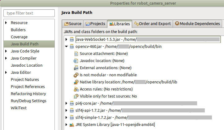
To use the Java code, you need to associate this program with the OpenCV libraries (and indicate the location of the native libraries) for the camera, pi4j to access GPIO port, Java-Websocket, slf4j-api et slf4j-simple for the Web serveur. You also need to import the 'index.html' page.
The source code is divided into three packages:
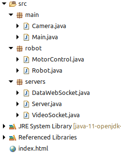
- Package main:
This package contains classes Main and Camera:
- class Main initializes the different modules of the program and les différents modules du programme and organizes the whole process. At start up, the function main automatically detects whether the program is running on the Raspberry Pi or a PC, in order to enable or disable GPIO port functionalities. It also contains a function for processing user commands from the Web interface, clientCommand(String command), and to send messages to the Web interface, broadcast(String msg).
- class Camera initializes webcam parameters and loads OpenCV libraries. On a Raspberry Pi, the libraries will be loaded from the path indicated by the 'path' variable in the Main class. On a PC, the libraries will be loaded from the system's default path defined during OpenCV installation. the function read() grabs a new webcam image, and the function Mat2bufferedImage() converts the image from OpenCV's Mat format to BufferedImage format.
- Package robot:
This package contains classes dedicated to motor control via the GPIO port: Robot and MotorControl. These classes are similar to those in the robot_motor_test program.
- classe Robot contains functions to control the robot: setMotors(int l, int r) defines the speed and direction for ech motor (l=left, r=right) with a speed between -100 et +100. The function stop() stops the two motors. The function move(int l, int r, int time) makes the robot moving for a defined time (in milliseconds).
- classe MotorControl initializes and manage the GPIO port. On initialization, the pins connected to the motor board are defined as outputs, and the signals used for PWM commands are defined. The function setMotor(int vg, int vd) controls the two motors (values between -100 and +100) and the function stop() stops the two motors.
- Package servers:
This package manages the Web server hosting the HTML page and handles communication with the client. It contains the following classes:
- class Serveur manage the Web server itself. On initialization, it detects the system's IP address (displayed on the console) and initializes websockets to communicate with the client. An internal class, ServerHandler, receives client requests and sends the 'index.html' page. The function stop() allows to properly shut down the server and its modules. The function broadcast(String msg) allows sending messages and commands to the Web interface.
- class DataWebSocket defines and manages a websocket to communicate with the Web interface. The function onMessage(WebSocket conn, String message) receives commands from the Web interface and forwards them to the class Main for processing.
- class VideoSocket defines a socket to send a video stream. the function pushImage(BufferedImage img) send an image with format BufferedImage to the Web interface. This class runs a separate thread that executes this function every 50 milliseconds, enabling a constant video stream.
HTML page:
The 'index.html' page describes the web page as it should be displayed in the Web browser. The top part displays the framerate. The central part is an image that takes the Java program's video socket as its source, enabling continuous display of the camera's video stream. The lower part contains a set of buttons for controlling the robot and stopping the program remotely. In the header, a block of CSS code provides the layout.
The page also includes a javascript section. When the page is opened, this code retrieves the server's IP address to connect to the video stream. A function enables commands from the server to be received and processed, as well as functions associated with the page's buttons. The communication protocol defines the following commands:
- commands from server:
framerate 20 : displays the program's frame rate (in this case, 20fps) at the top of the page.
- commands from client to the serveur:
robot forward : command to move the robot forward
robot backward : command to move the robot backward
robot turnleft : rotate the robot to the left
robot turnright : rotate the robot to the right
robot stop : command to stop the robot
system stop : command to remotely stop the program
Tracking a colored object:
This program is based on the previous project, but adds a simple primary color detection algorithm to enable the robot to orient itself towards a colored object.
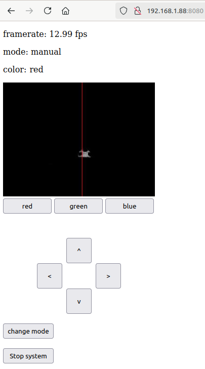
Automatic mode: the robot orients itself towards a colored object (in this case, red).
Source code:
- HTML page: index.html (right-click -> Save link as)
- Jar file: robot_camera_color.jar
- Java code: robot_camera_color.zip
As before, it is advisable to create a specific subfolder for this project. On the SSH console (or directly on a remote desktop), for example, you can create the folder with the following commands:
						cd ~/Java

						mkdir robot_camera_color

						cd robot_camera_color
Then, from the PC, we open a new console in the folder where the JAR and HTML files are located, and enter the following SCP commands, with the Raspberry Pi's IP address and password:
						scp robot_camera_color.jar pi@192.168.1.10:/home/pi/Java/robot_camera_color

						scp index.html pi@192.168.1.10:/home/pi/Java/robot_camera_color
From the SSH console (or from a console on a remote desktop), run the program with the following command:
sudo java -jar robot_camera_color.jar
The web server starts up, then displays its address in the SSH console, which you can enter in the address bar of a web browser. The robot can then be controlled using the arrow keys. The video stream shows color detection. You can select the color to be searched for (red, green or blue) using the three buttons below the video stream. The 'change mode' button is used to switch from manual to automatic mode and vice versa (the top display shows the current mode and color). In automatic mode, the robot turns towards the most important colored object in its field of vision. Stop the program by clicking on the 'stop system' button (or, from the SSH console, by pressing Ctrl+C).
To use the Java code, this program must be linked to the same libraries as the robot_camera_server project: OpenCV, pi4j, Java-Websocket, slf4j-api and slf4j-simple. Do not forget the 'index.html' page.
The source code is divided into four packages:
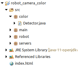
- Package main:
This package contains classes Main and Camera :
- class Main: compared to the robot_camera_server project, this class adds the color detection sub-module, and defines the robot's operating mode (manual or automatic). The image sent to the video socket is here the image generated by the color detection module. the function clientCommand(String command) defines a set of new commands to change the operating mode and the color to be detected.
- class Camera: no difference with the project robot_camera_server.
- Package robot:
This package contains the classes Robot and MotorControl :
- class Robot adds a function action(int px) allowing to autonomously control the robot according to the position of on aobject on the image (px).
- class MotorControl: no difference with the project robot_camera_server.
- Package servers:
This package contains the classes Serveur, DataWebSocket and VideoSocket, all three are identical to the project robot_camera_server.
- Package color:
This package contains the class Detector, which detects pixels of a certain primary color in the image. The function detect(Mat img) detects the position of a colored object on the image, and the function Matrix2bufferedImage() generates the output image with format BufferedImage that is sent to the Web interface.
Color is detected by comparing the values of a pixel's three color channels. For example, to detect the color red, the pixel value will be: val=max(0,rouge - vert - bleu). In this way, only pixels with a strong red dominance will be detected.
To detect the horizontal position of a colored object, we accumulate the pixel values of the same column, The column px with the greatest value gives the object's orientation.
HTML Page:
The 'index.html' page of this project adds, at the top, a line about the robot's operating mode (manual or automatic) and on the selected color (red, green or blue). The image received is the one generated by the color detection module. Below the image, three buttons allow selecting the primary color to be searched. At the bottom, a button is added to change the robot's operating mode.
The javascript section adds functions for additional buttons and enables the reception of two new commands.
The communication protocol defines the following commands :
- commands from server:
framerate 20 : displays the program's frame rate (in this case, 20fps) at the top of the page.
mode automatic : displays the operating mode ('automatic' or 'manual') at the top of the page.
color red : displays the selected color ('red', 'green' or 'blue') at the top of the page.
- commands from client to the serveur:
robot forward : command to move the robot forward
robot backward : command to move the robot backward
robot turnleft : rotate the robot to the left
robot turnright : rotate the robot to the right
robot stop : command to stop the robot
changemode : change the robot's operating mode
system red : change the desired color ('red', 'green' or 'blue')
system stop : command to remotely stop the program
Tracking of a vertical barcode:
This program is based on the robot_camera_server project, but adds an algorithm for detecting vertical barcodes. By knowing the size of the barcode, it is possible to define its distance, and therefore its position relative to the robot.
source code:
- HTML page: index.html (right-click -> Save link as)
- Barcode template: barcode.svg (right-click -> Save link as)
- JAR file: robot_camera_barcode.jar
- Java code: robot_camera_barcode.zip
As before, it is advisable to create a specific subfolder for this project. On the SSH console (or directly on a remote desktop), for example, you can create the folder with the following commands:
						cd ~/Java

						mkdir robot_camera_barcode

						cd robot_camera_barcode
Then, from the PC, we open a new console in the folder where the JAR and HTML files are located, and enter the following SCP commands, with the Raspberry Pi's IP address and password:
						scp robot_camera_barcode.jar pi@192.168.1.10:/home/pi/Java/robot_camera_barcode

						scp index.html pi@192.168.1.10:/home/pi/Java/robot_camera_barcode
From the SSH console, run the program with the following command:
sudo java -jar robot_camera_barcode.jar
By default, in automatic mode, the robot follows the first barcode detected in the image. To specify a particular barcode, enter its code as a parameter (number between 0 and 15):
sudo java -jar robot_camera_barcode.jar 9
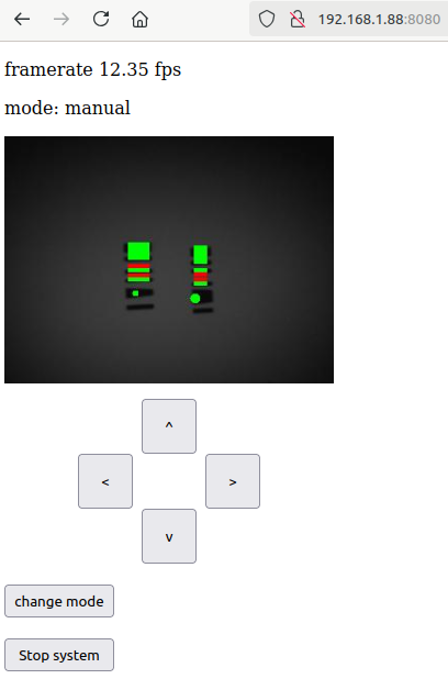
The web server starts up, then displays its address in the SSH console, which you can enter in the address bar of a web browser. The robot can then be controlled using the arrow keys. The video stream shows the detection of the barcode(s). The 'change mode' button is used to switch from manual to automatic mode and vice versa (the display at the top indicates the mode). In automatic mode, the robot orients itself towards the specified code (or, by default, the first barcode detected). Stop the program by clicking on the 'stop system' button (or, from the SSH console, by pressing Ctrl+C).
To use the Java code, this program must be linked to the same libraries as the robot_camera_server project: OpenCV, pi4j, Java-Websocket, slf4j-api and slf4j-simple. Do not forget the 'index.html' page.
The source code is divided into four packages:
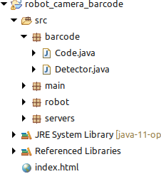
- Package main:
This package contains classes Main and Camera :
- class Main: compared to the robot_camera_server project, this class adds the barcode detection sub-module, and defines the robot's operating mode (manual or automatic). The image sent to the video socket is here the image generated by the barcode detection module. The function clientCommand(String command) defines a set of new commands to change the robot's operating mode.
- class Camera: no difference with the project robot_camera_server.
- Package robot:
This package contains classes Robot and MotorControl :
- class Robot adds a function action(int px, int height) allowing autonomous robot control based on the position and apparent size of a barcode on the image.
- class MotorControl: no difference with the project robot_camera_server.
- Package servers:
This package contains classes Serveur, DataWebSocket and VideoSocket, all three are identical to the project robot_camera_server.
- Package barcode:
This package contains classes Detector and Code, which enable barcode detection. The class Detector contains the detection algorithm. It scans the image column by column and detects the barcode markers. When a barcode is detected, it is registered using a code object instance containing its size and position properties. Instances with the same identification code are merged. The instance is used to define the barcode's center, apparent height and position. The class Code contains functions for reading the barcode, including its bianary identification code and orientation. The function Matrix2bufferedImage() generates the BufferedImage format image that is sent to the Web interface.
HTML page:
The 'index.html' page of this project adds a line on the robot's operating mode (manual or automatic) at the top. The image received is that generated by the barcode detection module. The lower part adds a button to change the robot's operating mode.
The javascript section adds functions for additional buttons and enables the reception of a new command.
The communication protocol defines the following commands :
- commands from server:
framerate 20 : displays the program's frame rate (in this case, 20fps) at the top of the page.
mode automatic : displays the operating mode ('automatic' or 'manual') at the top of the page.
- commands from client to the serveur:
robot forward : command to move the robot forward
robot backward : command to move the robot backward
robot turnleft : rotate the robot to the left
robot turnright : rotate the robot to the right
robot stop : command to stop the robot
changemode : change the robot's operating mode
system stop : command to remotely stop the program
ARTags tracking:
This program takes the robot_camera_server project, but adds an algorithm for detecting and following ARTags markers. The robot can then follow a predefined sequence of markers to follow a path.
The robot follows a sequence of two ARTags, with code 404 and 33, moving towards an ARTag until its apparent height exceeds 110 pixels, then moving toward the next ARTag. Once the sequence is complete, the robot follows the first distant ARTag it detects. The ARTag detector binarizes the image with a randomly varying threshold until it detects the marker it's looking for.
Source code:
- Page HTML : index.html (right-click -> Save link as)
- tag template: ARTag.svg (right-click -> Save link as)
- JAR file: robot_camera_ARTag.jar
- Java code: robot_camera_ARTag.zip
Note: the ARTag marker must have an even number of black squares: the detector uses the parity bit principle to eliminate certain false positives.
As before, it is advisable to create a specific subfolder for this project. On the SSH console (or directly on a remote desktop), for example, you can create the folder with the following commands:
						cd ~/Java

						mkdir robot_camera_ARTag

						cd robot_camera_ARTag
Then, from the PC, we open a new console in the folder where the JAR and HTML files are located, and enter the following SCP commands, with the Raspberry Pi's IP address and password:
						scp robot_camera_ARTag.jar pi@192.168.1.10:/home/pi/Java/robot_camera_ARTag

						scp index.html pi@192.168.1.10:/home/pi/Java/robot_camera_ARTag
From the SSH console, run the program with the following command:
sudo java -jar robot_camera_ARTag.jar
By default, in automatic mode, the robot follows the first 'distant' marker (smaller than 110 pixels in height) it detects in the image. To specify a sequence of markers to follow, specify them as parameters:
sudo java -jar robot_camera_ARTag.jar 404 33
The web server starts up, then displays its address in the SSH console, which you can enter in the address bar of a web browser. The robot can then be controlled using the arrow keys. The video stream shows the detection of the ARTags marker(s), with their code and apparent height. The 'change mode' button switches from manual to automatic mode and vice versa. In automatic mode, the robot rotates on itself until it finds the next ARTag marker in the sequence, then moves towards it. When the marker is close enough, it searches for the next marker, and so on. When the sequence is complete (or when no sequence is defined), the robot heads for the first marker it detects. You can restart the sequence by clicking on the 'initialize' button, and stop the program by clicking on the 'stop system' button.
To use the Java code, this program must be linked to the same libraries as the robot_camera_server project: OpenCV, pi4j, Java-Websocket, slf4j-api and slf4j-simple. Do not forget the 'index.html' page.
The source code is divided into four packages:
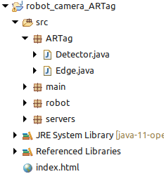
- Package main:
This package contains classes Main and Camera :
- class Main: compared to the robot_camera_server project, this class adds an ARTag detection sub-module, and defines the robot's operating mode (manual or automatic). The image sent to the video socket is the image generated by the ARTags detection module. The function clientCommand(String command) defines a set of new commands to change the robot's operating mode.
- class Camera: no difference with the project robot_camera_server.
- Package robot:
This package contains classes Robot and MotorControl :
- class Robot adds the function action(int px, int pz, boolean search) allowing the robot to be controlled autonomously according to the position and apparent size of a marker on the image, and whether the robot is searching for a marker or not.
- class MotorControl: no difference with the project robot_camera_server.
- Package servers:
This package contains classes Serveur, DataWebSocket and VideoSocket, all three are identical to the project robot_camera_server.
- Package ARTag:
This package contains classes Detector and Edges, which enable the detection of ARTags markers.
- class Detector contains a contour detection algorithm and a function Matrix2bufferedImage() that generates the image with format BufferedImage that is sent to the Web interface.
. The algorithm performs the following steps:
- Image binarization
- Detection of edge points
- Detection of edges
The detector filters edges that are too small to be exploited, the remaining adges are recorded as instances of object Edge.
- class Edge detects whether an edge is actually an ARTag, and, if so, decodes its binary identifier. The algorithm performs the following steps:
- Corner detections (FAST Algorithm)
- Elimination of edges with more or less than 4 corners
- Elimination of quadrilateral that are not squares
- Rectification of tag's image
- Reading color of the 9 inner squares
- Elimination of tags with odd number of black squares
- Decoding the binary code of the tag
HTML page:
The 'index.html' page of this project adds a line on the robot's operating mode (manual or automatic) and on the code of the currently tracked ARTag (-1 if none). The image received is that generated by the ARTag detection module.The lower part adds a button to change the robot's operating mode, and a button to reinitialize the sequence of ARTags.
The javascript section adds functions for additional buttons and enables the reception of two new commands.
The communication protocol defines the following commands :
- commands from server:
framerate 20 : displays the program's frame rate (in this case, 20fps) at the top of the page.
mode automatic : displays the operating mode ('automatic' or 'manual') at the top of the page.
target 33 : displays the code of the currently tracked ARTag (here, tag 33) at the top of the page.
- commands from client to the serveur:
robot forward : command to move the robot forward
robot backward : command to move the robot backward
robot turnleft : rotate the robot to the left
robot turnright : rotate the robot to the right
robot stop : command to stop the robot
changemode : change the robot's operating mode
system initialize : réinitialize the sequence of ARTags
system stop : command to remotely stop the program