Johnny 2.0 simulator
Ressources :
- Johnny2_simu_Cpp.7z: C++ sources
(requires OpenCV library)
- Johnny2_simu_Java.7z: Java sources
- Johnny2_simu.jar: executable jar
Description :
This simulator allows to observe the behavior of Johnny 2.0 in two light conditions, light at the center and light on edges, while analyzing parameters and internal variables of the robot. It is also possible to modify some of these parameters during the simulation, such as synaptic weights, and to provide “rewards” and “punishments” to influence the behavior of the robot.
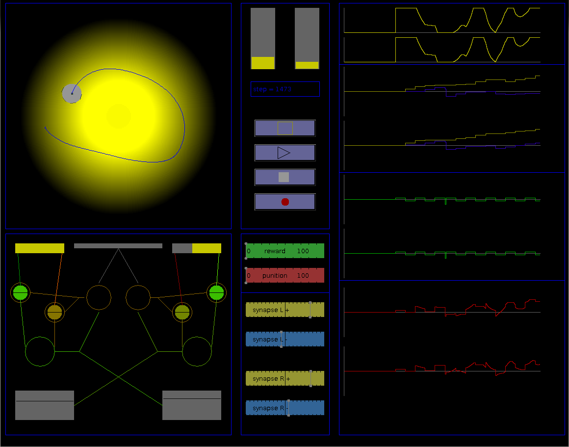
simulation display:
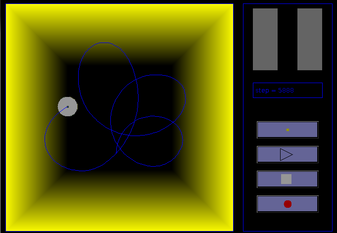
- Environment
Several information and buttons are displayed on the right of the environment, allowing to control the simulation:
- light sensor values: these histograms indicate the amount of light received by each sensor.
- step display: indicates the number of simulation cycle since the beginning of the simulation.
- light change button: allows to change light conditions: light on the center (by default) and light on edges. This change allows to test the adaptation possibilities of the robot.
- start/pause button: starts or pauses the simulation.
- stop button: stop and reinitialize the simulation. The step counter is reset to 0.
- record button: when activated, the simulator write, at each step, internal values in a text file
Johnny2_simu.txt. Each line has the following form:step sensorL sensorR bumper motorL motorR astrocytL astrocytR synapseL+ synapseL- synapseR+ synapseR- internal_valueL internal_valueR light_condition
- Neural network
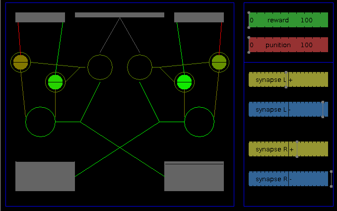
On the right of the network, several sliders allows to visualize and modify internal values:
- reward and punishment make it possible to attribute a reward or punishment value that will be integrated on the next astrocyts value change. They influence the learning process independently of internal values.
- synapses: these sliders display current values of the four synaptic weights of the network (left exciter, left inhibitor, right exciter, right inhibitor), and allows to modify them.
- Internal value curves
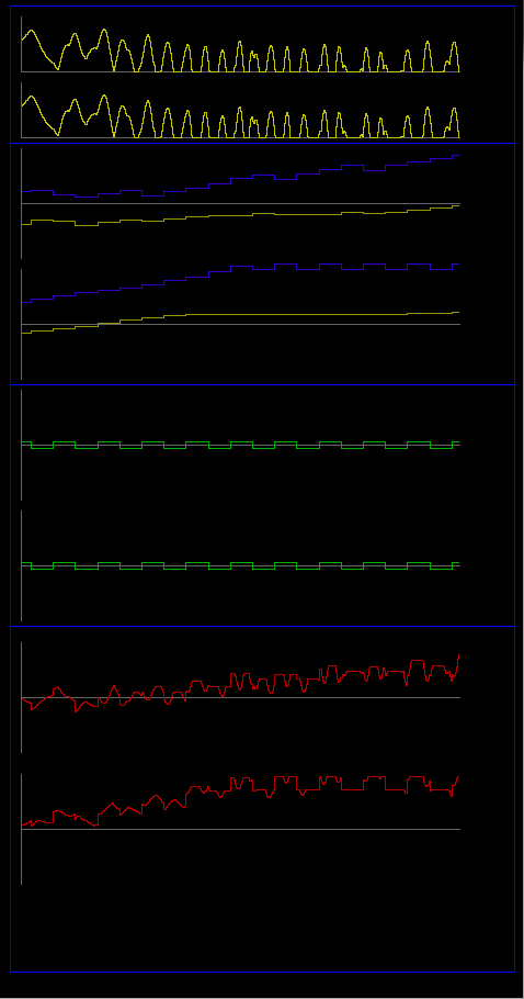
- values of left and right light sensors (yellow)
- values of left synapses, exciter (yellow) and inhibitor (blue)
- values of right synapses, exciter (yellow) and inhibitor (blue)
- output values of left and right astrocyts (green). This values are added to synaptic weights. Unlike the physical robot, when the internal value of astrocyts becomes negative, the frequence and amplitude increase to let the robot testing solutions faster. This variation was not implemented in the physical robot due to limitations of its microcontroller.
- speed of the left and righ motors (red)
Experiments:
At the beginning, the robot progressively increases its speed, then bumps in a wall. After several collisions, it associates collision with absence of light, and becomes photovore and turns around the light source (0:30). Then, as the sensor on the side of obscurity doesn't allow to detect collision, the robot get a half-photovore behavior using only one sensor (0:55) and turns around the light source in the other direction. After several turns without collision, it moves again in dark areas (1:30), and the cycle restarts. We then change light conditions (1:53). The robot, as a photovore, moves toward a wall. After a collision, it moves slowly, and finally becomes photophobe and stays away from enlighten walls (2:35).