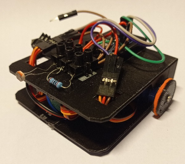
Description:
MERWOL and MERWIL are two small, minimalist robots designed to illustrate the principle of enactivism, which enables a robot or artificial agent to actively perceive its environment. These two robots are identical, differing only in their programming. MERWOL stands for 'Minimal Enactivist Robot WithOut Learning', and illustrates the principle of enactivism, but does not use learning mechanism. MERWIL stands for 'Minimal Enactivist Robot WIth Learning', and as its name suggests, uses a learning mechanism. These robots are equipped with a small board based on a ATTiny85 microcontroller, and a single light sensor to move towards the strongest light source.
List of components:
- Digispark ATTiny85 micro USB bard
- 2 servomotors SG90
- Battery 18650 with plug
- screw terminal
- photoresistor (LDR)
- resistor of 2000Ω
- jumper wires
- 3D-printed chassis
- 2 rubber bands
- felt pad
The robots use a Digispark board based on an ATTiny85 microcontroller. This microcontroller has 5 inputs and outputs (6 using the RESET port with a trick), which is sufficient for this robot, which uses only three of them. It can operate with a voltage range from 2.7V to 5.5V, allowing to power it directly from the 18650 battery, which has a nominal voltage of 3.7V and a maximum voltage (full charge) of 4.2V.
Propulsion is provided by two SG90 servomotors, modified for continuous rotation. This trick makes possible to control speed and direction of rotation with a single pin, with the control electronics fully integrated in the servomotor case.
Robot assembly:
We start by modifying the two servomotors for a continuous rotation:


Sketch for servomotor calibration. The shaft turns in one direction, then the other, and stops in the neutral position (90°).
- sketch for ATTiny85 : servo_test_AT85.ino (see next section for uploading)
- sketch for Arduino : servo_test_Arduino.ino
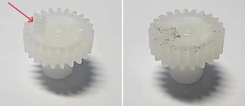
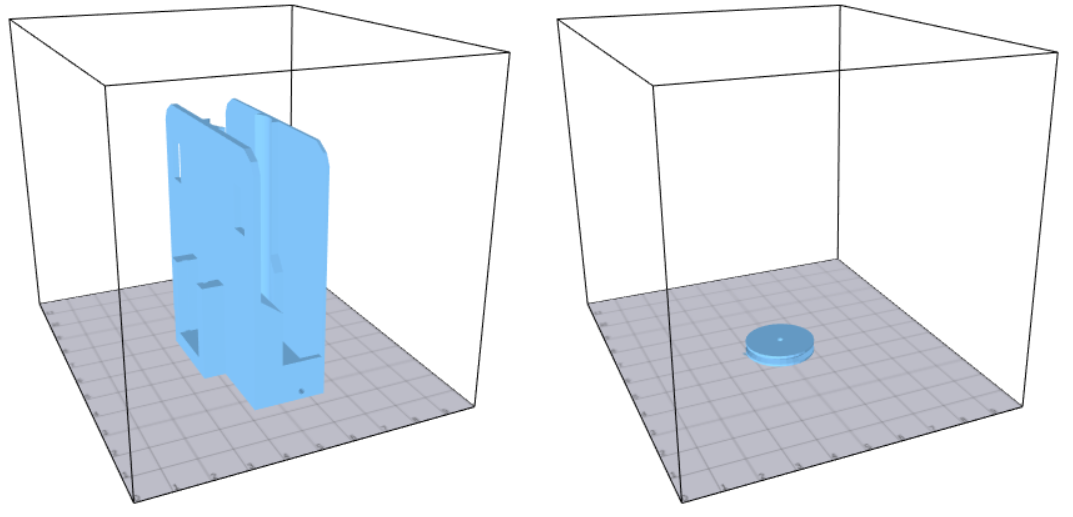
The chassis and wheels are printed from the following models. These models can be printed by low-volume printers (10x10x10cm) and do not require supports. However, a raft is recommended.
- Chassis: merwol_base.stl
- Wheel: merwol_wheel.stl
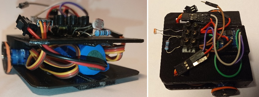
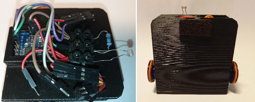
The robot can then be assembled:
- First, insert the battery into the battery slot in the center of the robot.
- The two servomotors are inserted into their slots, with the cables facing forward. If the servomotors don't fit properly, one or more layers of adhesive tape can be added to slightly increase their thickness.
- The connector for the left servomotor is brought out through the left opening, and the connectors for the right servomotor and battery through the right opening. Servomotor cables must be coiled in the space inside the chassis.
- The connectors are soldered to the ATTiny85 board, then the board is inserted into its slot on top of the robot, with the USB connector facing forward.
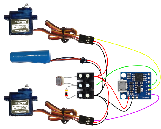
- The components are then wired around the screw terminal. Some jumper wires can be cut in half for power and ground lines.
- Add the wheels to the motor axles, screw them in place with shaft screws, then fit the rubber bands to act as tires. Finally, add a felt pad to the front, under the robot.
How to use the robot:
Programming the ATTiny85 requires the installation of a few extensions to the Arduino IDE. First of all, you need to add this microcontroller to the IDE's board manager:
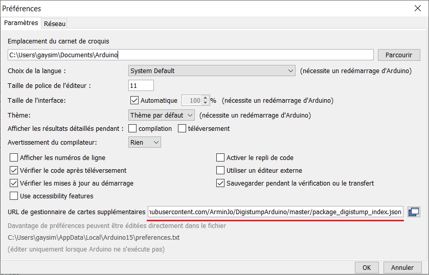
- access the IDE parameters (File->Preferences), then, in the 'URL for additional map manager' field, add the following link :
https://raw.githubusercontent.com/ArminJo/DigistumpArduino/master/package_digistump_index.json
- Next, download the board templates: open the Board Manager (Tools->Board type->Board Manager). Then search for and install the 'ESP32 by Expressif Systems' boards.

- We can now choose the 'Digispark' board model. The microcontroller can operate at frequencies from 1 to 16.5Mhz (the 16.5Mhz frequency enables communication with a PC via USB serial port).
Uploading an .ino sketch on ATTiny85 differs slightly from uploading on an Arduino. First, make sure the battery is not connected. To start uploading, first disconnect the board from USB port, then click on the upload button. Connect the board only when the message “Plug in device now...” appears.
Once the sketch has been uploaded, disconnect the USB cable and simply connect the power cable to the battery. The program starts after a 5-second delay. To switch off the robot, disconnect the battery.
An enactivist robot:
Enactivism describes the perception we have of our environment as an active process that begins with an experience we perform on this environment, perception being the result of this experience. For example, to know whether an object is solid or soft, we squeeze it, the object's sotftness being obtained by the resistance felt when squeezing it. Considering action in the perception process increases the information we can obtain about the environment, even with a small number of sensors.
The MERWOL and MERWIL robots illustrate this principle: these robots use a single light sensor to find a light source. Simple perception via this sensor is insufficient to know whether the light source is to the right or left of the robot. However, if we consider the robot's movement, we can tell whether the light is increasing or decreasing, and thus whether we're turning the right way or not.
With a classical perception, at least two light sensors are needed to know on which side the source is. The system starts with a perception, to retrieve values of the sensors. The robot analyzes these values and makes a decision according to its program. Finally, it performs an action: turn to the right or turn to the left. So we have the decision cycle perception->decision->action
MERWOL and MERWIL have just one sensor, but they integrate action into their perception. The robots start with a randomly chosen action (e.g. turn right). Then, they observe the result of their action on their sensor: brightness may increase or decrease. If the light increases, they continue to turn right; if it doesn't, they change direction and turn left. And the cycle starts all over again.
Since we can't separate an experiment from its result, we create action/perception couples, which we call Interaction. Here, we have two possible actions: moving forward by turning right or left (activating the right or left motor), and two possible results: luminosity increases or decreases. We can then create 4 interactions:
- (right;increase), noted r+
- (right;decrease), noted r-
- (left;increase), noted l+
- (left;decrease), noted l-
When the robot performs an interaction, for example r+, it will move forward by turning to the right. If the light source is on the left, the value obtained by the sensor will decrease, which leads to the enactment of the interaction r-. The interaction r+ is therefore a failure. The next decision takes into account the enacted interaction r-, which, from an external point of view, indicates that the light source is on the left, and attempts the interaction l+. This time, it is indeed this interaction that is enacted: the interaction is a success.
We can then define, based on the observed interaction, which interaction can be attempted, either to perform a particular interaction, or simply obtain information about the environment. Learning models can be used to try to predict which interactions can be performed after previous interactions, such as the sequential models developed by Olivier Georgeon, or parallel models developed during my thesis.
The decision cycle of the enactivist robot is thus different from that used with a classical perception. Here, the cycle is decision->result->decision->result, or, more simply, interaction->interaction.
The MERWOL robot:
MERWOL is a robot that perceives its environment through its interactions. However, the selection of the next interaction is not based on a learning mechanism, but on simple decision rules. :
- if r+ then r+ (continue to turn right)
- if r- then l+ (change and turn left)
- if l+ then l+ (continue to turn left)
- if l- then r+ (change and turn right)
The robot moves forward, turning in one direction as long as the brightness increases, then changes direction when it decreases. The robot thus moves in a zig-zag pattern towards the light source.
source code of MERWOL: MERWOL_AT85.ino
In this program, each interaction is defined with a 2-bits binary code:
r+ = 00
r- = 01
l+ = 10
l- = 11
This encoding simplifies interaction management: the action can be obtained, and the result can be written with bitwise operations:
(intended & 0b10) == 0 to obtain the action,
enacted = (intended & 0b10) or enacted = (intended | 0b01) to get the enacted interaction according to enaction's result.
Enacted interactions are stored on a timeline consisting of a single byte. For each new interaction, a two-bits left shift is performed, then the two bits of the new interaction are written:
timeline = timeline<<2;
The last four interactions enacted are thus stored.
timeline = timeline | enacted;
The photoresistor is read four times, the final value being the average of these four measurements. This reduces the noise measured by the microcontroller's analog-to-digital converter.
The MERWIL robot
MERWIL is a robot identical to MERWOL, but adds a rudimentary learning mechanism to select the next interaction. This learning mechanism is derived from the IMOSHEM learning mechanism developed by Olivier Georgeon. However, it has been simplified to the extreme to fit on the low memory of the ATTiny85.
The IMOSHEM (Intrinsically MOtivated SHEma Mechanism) model is based on two principles:
- The principle of sensorimotor schemes: when a sequence of two interactions is often observed, we can consider that if the first interaction has been enacted, then the second has a strong chance of being enacted in turn. The learning mechanism will thus construct sequences of two interactions, called schemes. A scheme can then be enacted as an interaction, which allows the construction of higher-level schemes. The enacted and enacting schemes provide information on the current situation of the robot, defining an implicit model of the environment. The schemes whose first part has just been enacted can also propose the second part to the decision system, providing a list of candidate interactions or schemes that can probably be enacted.
- The principle of interactional motivation: as the IMOSHEM model aims at the emergence of behaviors without knowledge about the environment, we cannot define a reward according to a predefined goal, but only a form of internal (or intrinsic) motivation that depends only on the learning model. The IMOSHEM model introduces a new form of intrinsic motivation related to interactions: interactional motivation. This form of motivation associates to each interaction a numerical value, called valence, which defines inborn behavioral preferences, that the agent or robot 'feels' when it successfully enacts an interaction. The decision mechanism must then generate behaviors that lead to situations where high-valence interactions can be enacted.
MERWIL's decision mechanism simplifies this model to the bare minimum:
- We first define the behavioral model of the robot with valences:
r+ -> 1
r- -> -1
l+ -> 1
l- -> -1
Thus, the robot 'likes' to move toward light and 'dislikes" moving away.
- Schemes are here limited to a length of two interactions: we thus won't be able to build higher-level schemes. This limits the number of possible schemes to 16, which can be encoded with a 4-bit binary code, with the two most significant bits indicating the first interaction of the scheme, and the two least significant bits the second. Scheme properties can be stored in arrays of size 16, with the scheme's code providing index to the corresponding array cell. Scheme propositions are limited to the 4 interactions. Arrays of size 4 are used to store interactions' properties and to calculate propositions' values.
source code of MERWIL: MERWIL_AT85.ino
Description of the algorithm:
The first step is to count the number of times a scheme has been observed. We use an integer array counters of size 16. Each time an interaction has been enacted and recorded in the timeline (see MERWOL description), we use the four least significant bits of the timeline variable to identify the scheme, and increment the corresponding cell in counters:
counters[ timeline & 0b1111 ]++;
The value of a proposed interaction is defined as the sum of counters of the schemes that proposed this interaction, multiplied by the valence of the interaction. We then add the values of the alternative interactions, that are interactions that can be enacted instead, in case of failure. Thus, for each interaction, the alternative interactions must be recorded. Here, we use the fact that each interaction has at most one alternative, allowing the use of a byte array alternative of size 4. An alternative is recorded in case of failure of the intended interaction:
if (enacted!=intended) alternative[intended] = (enacted | 0b1000);
We use here the fourth bit to indicate that an alternative interaction has been observed (as the code 00 usually defines interaction d+).
We then collect the propositions of the schemes whose first interaction corresponds to the last enacted interaction. We must therefore make a right shift of two bits on the code i of a scheme to get the code of the first interaction:
(timeline & 0b11) == ( i & 0b1100 )>>2
We then compute the values of propositions, that are accumulated in an integer array candidates of size 4:
							 for (i=0;i<4;i++) candidates[i]=0;	// reinitialization

							 for (i=0;i<16;i++){	// read the 16 schèmes

							   if ( (timeline & 0b11) == ( i & 0b1100 )>>2 ){	// detection of 'active' schemes

							     if ( (i & 0b01) == 0 ) candidates[(i & 0b11)] += counters[i]; // valence = 1

							     else   candidates[(i & 0b11)] -= counters[i]; // valence = -1

							   }

							 }
We add the values of alternatives (if any). We use a second integer array candidates2 of size 4:
							 for (i=0;i<4;i++){ // read the 4 propositions

							   candidates2[i]=candidates[i]; // get the proposition's value

							   if ( (alternative[i] & 0b1000) !=0 )

							     candidates2[i]+=candidates[alternative[i] & 0b0011];

							 }
Finally, we select the proposition with the greatest value:
							int maxVal=candidates2[0];

							intended=0;

							 for (i=0;i<4;i++){

							   if (candidates2[i]>maxVal){

							     maxVal=candidates2[i];

							    intended=i;

							   }

							 }
A new enaction cycle can then begin with the new intention interaction.
MERWIL 'gropes' a little at first, but quickly learns how to act to get closer to the light source.
Simulation of MERWOL and MERWIL robots
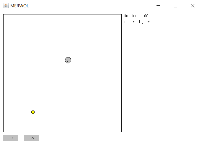
These programs written in Java simulate the robots in a virtual environment. The robot is represented with a gray circle, the light source with a yellow disk. It is possible to move the light source by clicking in the frame limiting the environment. At the bottom, two buttons allow you to control the simulation: play/pause to play or pause the simulation, step to play the simulation interaction by interaction.
The pane on the right displays the agent's properties. In the case of MERWOL, the window displays the timeline of the last two enacted interactions in binary format, which also corresponds to the code of the last enacted schema, and the last four interactions in the form of symbols.
executable JAR file: MERWOL_simu.jar
Java source code: MERWOL_simu.zip
Javascript version: MERWOL_javascript.html
MERWIL's simulator also displays the timeline in binary and symbol format. Below, the 16 possible schemes are displayed: binary code, number of enactions, and, if available, the proposed interaction. Below, the 4 interactions are displayed: binary code, value of propositions, code of the discovered alternatives, and final value of propositions. This display makes it possible to follow the robot's learning process over time.
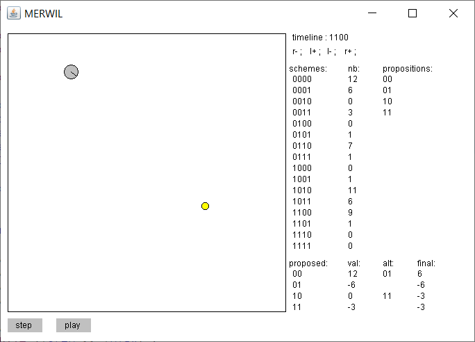
executable JAR file: MERWIL_simu.jar
Java source code: MERWIL_simu.zip
Javascript version: MERWIL_javascript.html